What's Hot
    Facebook Twitter Instagram
    Delta Sigma CompanyDelta Sigma Company
    • About
    • Electromagnetics
    • Factory Automation
    • Mixed Reality
    • Learn
      1. Factory Automation
      2. Electromagnetics
      3. Mixed Reality
      4. Course Catalogue
      5. About
      6. View All
      7. View All

      Using Machine Vision To Calibrate Countersink Depth On F-22 Aircraft

      Fuselage Rollover System

      Cargo Ramp Drill

      Automating An Old Drill & Rivet Machine

      Delta Sigma Company at AMTA 2024: Innovating Antenna Measurement Solutions

      A Squat Cylinder-Dihedral Dual Calibration Device for Compact Ranges at UHF

      Canonical Targets in R&D RCS Measurement Range Operations

      Using the Nyquist Sampling Criteria in Antenna and RCS Measurements

      How Gulfstream Paints Aircraft Using Mixed Reality

      Delta Sigma Company Announces Partnership With Zuken USA

      Delta Sigma Company at AMTA 2024: Innovating Antenna Measurement Solutions

      Advanced Robotics Automation Tools

      Advanced Robotics Automation Tools: Revolutionizing Factory Automation Services

      Robotics Automation: Tailored Solutions

      Robotics Automation: Tailored Solutions for Modern Businesses

      Expert Robotics Automation Services

      Expert Robotics Automation Services

      Delta Sigma Company at AMTA 2024: Innovating Antenna Measurement Solutions

      Advanced Robotics Automation Tools

      Advanced Robotics Automation Tools: Revolutionizing Factory Automation Services

      Robotics Automation: Tailored Solutions

      Robotics Automation: Tailored Solutions for Modern Businesses

      Expert Robotics Automation Services

      Expert Robotics Automation Services

      Delta Sigma Company at AMTA 2024: Innovating Antenna Measurement Solutions

      Advanced Robotics Automation Tools

      Advanced Robotics Automation Tools: Revolutionizing Factory Automation Services

      Robotics Automation: Tailored Solutions

      Robotics Automation: Tailored Solutions for Modern Businesses

      Expert Robotics Automation Services

      Expert Robotics Automation Services

      Using Machine Vision To Calibrate Countersink Depth On F-22 Aircraft

      Stacker / Drill Automation

      Using Machine Vision To Assemble The F-22 Fuselage

      Automating RCS Measurements For High-Speed Production Line In-Process Verification

    CONTACT
    Delta Sigma CompanyDelta Sigma Company
    Home»Learn»Using Machine Vision To Calibrate Countersink Depth On F-22 Aircraft
    • Factory Automation, Featured, Projects

    Using Machine Vision To Calibrate Countersink Depth On F-22 Aircraft

    Facebook
    Twitter
    LinkedIn

    Automating F-22 Aircraft Production

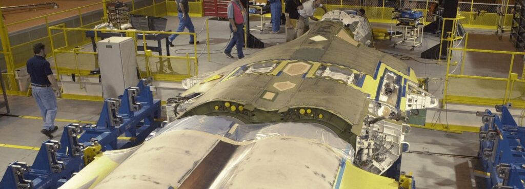
    The F-22 vertical stabilizer has a few thousand holes for fasteners that are drilled in a composite/composite stack or a composite/titanium stack. The hole diameters range from very small to quite large at the root. The absolute position of these holes requires a very high accuracy; however, the countersink depth is even more stringent. The countersink depth accuracy requirement is further complicated by the fact that the skin position tolerance is more than 10X greater than the countersink depth tolerance. Yet, the countersink depth is based on where the skin “is”, not where it “should have been”.

    Creating the program to position the drill head to drill all the holes is a relatively straightforward process, although the highly automated approach Delta Sigma took to this problem was not the traditional G-code approach. The plunge depth for the drill, however, is determined at every hole to ensure every hole has the perfect countersink. The drill bits used for this system have the countersink cut into the drill bit 0.9 inches up the shank when the bit is new. After resharpening, this value shrinks.

    A pressure foot with about 80-pounds of force surrounds the drill bit and has multiple functions:

    • Clear away any dust on the surface prior to contact
    • Compress the stack to minimize interlaminar burrs during the cut
    • Measure where the skin surface is in the drill-plunge coordinate system
    • Remove dust and chips during the cut

    Just before the pressure foot contacts the surface of the skin an air blast is emitted from the pressure foot to clear away any chips or dust particles that could be left on the skin from drilling a nearby hole. A single particle of composite dust under the pressure foot when it touches the surface can cause the required accuracy to be unmet. During the cut, a strong vacuum passes through the pressure foot to remove over 99% of the composite dust and titanium chips.

    The high compression force of the pressure foot causes the skin surface to move as the stack is compressed, or at least it can potentially move, so the plunge depth is a “moving target”. A dust particle in the spindle can cause the tool holder to be slightly displaced causing a countersink depth inaccuracy. Lastly, the location of the drill bit in the tool holder is another potential error source. Clearly, there are a lot of ways for an error to creep into the system, yet we need zero errors across thousands of holes of many sizes, stack depths, and materials.

    The pressure foot is measuring the location of the skin with an accuracy of 0.0005 inches every few milliseconds during the drill plunge. If the countersink part of the drill shank is known to have a similar tolerance relative to the pressure foot, very high accuracy countersinks are achievable very fast. This project was to develop a way to measure and calibrate the plunge axis of the drill system in a more direct way than the coupon trial-and-error method that had been historically used.

    Delta Sigma Company used a machine vision system Cognix DVT550 smart camera as the image source which also included all the necessary measurement tools. A telecentric lens was used to eliminate optical distortion; on the other side of the drill bit, the backlight source is a Cognex IDRA, red LED light with a diffuser face to provide an even field of illumination.

    Moving the drill head to a calibration position where the plunge axis would deploy into the calibration fixture which would push back the pressure foot, measure the angled lines on the countersink part of the drill, then calculate the intersection point of these lines. The vision system is calibrated to the pressure foot position, so the derived intersection point becomes the “calibration” value that will be used to ensure a perfect countersink depth. That calibration number is passed to the motion controller of the drilling machine via an ethernet connection.

    Each time a new drill bit is picked up, the drill system will move the drill head to the calibration fixture to measure and calibrate the drill bit. The user can send the system to repeat the calibration if there is any reason to suspect something has changed during a long use of one drill bit.

    Share.

    Related Posts

    Delta Sigma Company at AMTA 2024: Innovating Antenna Measurement Solutions

    Services

    A photo of a Compact Antenna Test Range (CATR) facility. The image shows a shielded room with an anechoic chamber, a robotic positioning system, and various measurement equipment, including spectrum analyzers and network analyzers. The control room can be seen through the glass window, where engineers and technicians can monitor the test results. CATR is used for testing and evaluating the performance of small and medium-sized antennas.

    RCS and Antenna Measurement Systems

    "An image of a modern factory utilizing automation services. The photo shows a variety of machines and equipment including robots, conveyor belts, and control systems. In the background, you can see a control room, where operators monitor and control the automation system. The factory floor is clean and well-lit, with workers in safety gear. The automation services aim to improve efficiency, reduce costs, and increase the speed and accuracy of the production process.

    Engineer to Order

    An airplane in the foreground with a projected paint masking pattern overlay, being assisted by ProjectionWorks technology. The technology is used to improve efficiency and accuracy in the paint masking process.

    Digital Thread / Digital Twin

    Editor’s Pick

    Fuselage Rollover System

    Cargo Ramp Drill

    Automating An Old Drill & Rivet Machine

    MENU

    • RADAR CROSS SECTION
    • FACTORY AUTOMATION
    • MIXED REALITY

    DISCOVER

    • ABOUT
    • LEARN
    • CAREERS
    • SITEMAP

    CONTACT US

    ADDRESS:
    2125 Barrett Park Dr #110
    Kennesaw, GA 30144

    PHONE:
    (770) 575 – 5100

    EMAIL
    info@deltasigmacompany.com

    FOLLOW US

    • Facebook
    • LinkedIn
    • Twitter
    • YouTube

    PRIVACY

    COPYRIGHT 2024 DELTA SIGMA COMPANY ALL RIGHTS RESERVED.

    Type above and press Enter to search. Press Esc to cancel.