The need to sample data
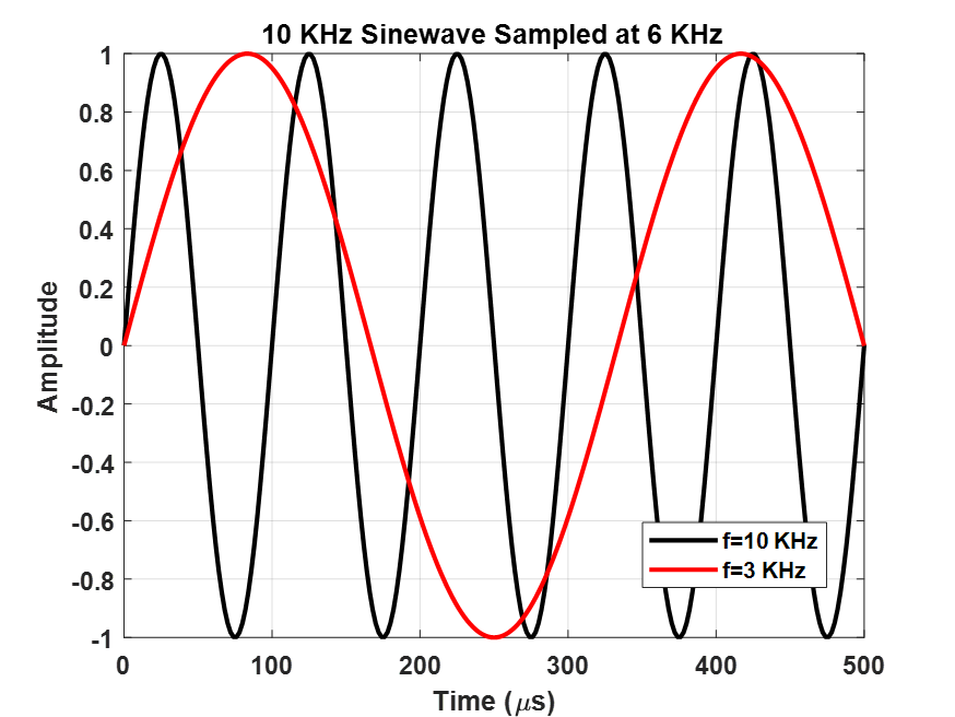
While the world moves continuously around us, the RF measurement world, especially the antenna and RCS measurement communities, collect magnitude and phase data in discrete steps. These discrete steps may be incremental times, frequencies, positions, and angles. A police radar gun samples in discrete time intervals, RF network analyzers step in frequency, field probes increment distance, and rotators permit travel in angular increments. The length of each increment in seconds, Hertz, meters, or radians, is an important factor in the execution of RF measurements. The relationship between the length of a measurement interval and its desired outcome is described by the Nyquist-Shannon Sampling Theorem, usually referred to as the “Nyquist Rate” or “Nyquist Criteria.” This relationship states that a sampled data sequence can completely represent all the information in a continuous version of the data if you sample at twice the highest frequency content in the continuous version. To illustrate this relationship, consider a continuous 10 KHz sine wave that’s sampled according to Nyquist as shown in Figure 1. The under sampling of the sine wave at 6 KHz, takes the original sine wave and makes it appear as though it’s at a much lower frequency. This is akin to sampling the incredible range of Freddie Mercury, the former lead singer of the rock band, Queen, and making him sound like Rush Limbaugh, the former radio talk show personality. Sampling at too long an interval does not capture all the frequency content within a signal.
How finely must I sample?
Nyquist revealed that to capture all the frequency content in a signal, the original signal must be sampled at a rate that’s twice the highest frequency content. This means that a sine wave of 10 KHz must be sampled at greater than 20 KHz or a sampling increment greater then τ=1⁄20000=50μs.
Since antenna and RCS measurements are performed under a variety of sampling methods, the Nyquist sampling rate must be tailored for each scenario, but usually this can be expressed as a phase change of no more than π radians for each increment. To illustrate this concept, four scenarios will be examined:
- Police Radar Stepped Time Measurement
- Compact Range Stepped Frequency Measurement
- Compact Range Stepped Angular Measurement
- Linear Field Probe Stepped Distance Measurement
Police Radar Stepped Time Measurement
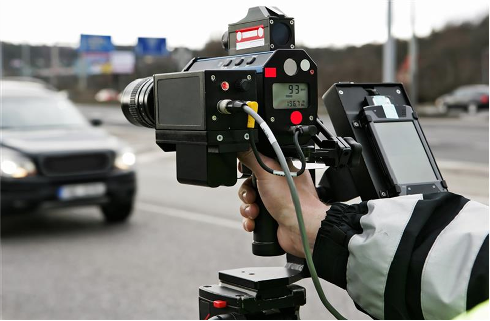
Police radars measure the change in phase that occurs from the backscatter of moving vehicles as shown in Figure 2.
The question is how often does the radar have to sample to adequately measure the vehicle’s velocity? If we represent the radar backscatter of a moving vehicle as a common point source at an instant in time, the return may be expressed as
$$\sigma=e^{(-j2\beta d)}$$
where σ is the measured backscatter, β is the wavenumber, d is the distance from the radar to the vehicle at one instance in time, and the coefficient of 2 accounts for a two-way travel time for the electromagnetic wave. The phase of the measured signal at two successive instants in time (negative sign is assumed and suppressed) is $$ϕ1=2βd_1\;and\;ϕ2=2βd_2.$$
The difference between the two successive phase measurements is $$\Delta\phi=2\beta\Delta d.$$
Since the Nyquist criteria states that the difference in successive samples must be less than radians, the phase increment is $$2\beta\Delta d<\pi.$$
Expanding this inequality, we have
$$2(2\pi/\lambda)\Delta d<\;\pi.$$
Simplifying and diving by the sampling increment Δt, and recognizing the velocity, v=Δd/Δt, the inequality may be expressed as
$$\Delta t<\lambda/(2v_max).$$
For a 10 GHz radar (λ=0.03m) detecting a maximum vehicle velocity of 90 m/s (~200 mph), the Nyquist sampling interval must be less than 167μs.
Compact Range Stepped Frequency Measurement
It is commonplace in antenna and RCS compact ranges to illuminate the target of interest with a stepped frequency waveform such as 2-18 GHz, every 10 MHz. A sample compact range taking stepped frequency and azimuth measurements is shown in Figure 3.
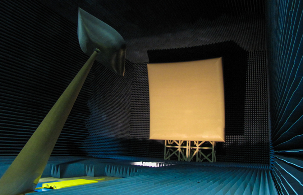
This increment depends entirely on what the operator wants to do with the recorded data. For example, beyond an incremental frequency choice, some range measurements are taken at a single frequency such as 10 GHz or a handful of selected frequencies across a desired spectrum. Isolated frequency measurements most often require no post-measurement processing. However, stepped frequency measurements most often are used to provide valuable information in the time domain by the Fourier Transform. The question is what frequency increment should be chosen such that the time domain yields the necessary information. Assuming that the scattering from a target is the superposition of point sources, we state the response of a single point source as
$$\sigma=e^{-j2\beta d}$$
where d is the distance from the center of the quiet zone along the centerline of the chamber, usually defined by reference to the calibration target whose response is also measured at the center of the quiet zone. The response from the point source can be expressed as
$$\sigma=e^{-j2(2\pi/\lambda)d}=e^{-j2\pi f(2d/c)}\;=e^{-j2\pi f\tau}$$
where f is the illumination frequency and τ is the two-way time along the centerline of the chamber as described by the one-way distance d. The phase of the measured response is
$$\phi=2\pi f(2d/c).$$
Using the Nyquist criteria, the incremental phase inequality due to a frequency increment may be expressed as
$$\phi_1=2\pi f_1(2d/c),\phi_2=2\pi f_2(2d/c)$$
$$\Delta\phi=2\pi\Delta f(2d/c)<\pi$$
$$\Delta f<c/4d.$$
Since the time spectrum is symmetric about the center of rotation, d is actually ±d. For a compact range to detect targets at a maximum extent of ±25 feet from the center of rotation. The Nyquist criteria requires a Δf of 10 MHz or less.
Compact Range Stepped Angular Measurement
Measurement that are angular dependent are just as common as those with frequency dependence. The question is how fine in angle does one have to measure to meet the Nyquist criteria? Our same point source expression is modified to represent the maximum down range extent from the center of rotation at a given angle. This can be written as
$$\sigma=e^{-j2\beta dsin\theta}.$$
Expressing the differential phase as an inequality we have
$$\phi=2\beta d\sin\theta$$
$$\phi_1=2\beta dsin\theta_1,\phi_2=2\beta dsin\theta_2$$
$$\Delta\phi=2\pi(2d/\lambda)\lbrack sin\theta_2-sin\theta_1\rbrack.$$
Since the start angle is arbitrary, we are free to assume that θ1=0, which leaves
$$2\pi(2d/\lambda)\sin\Delta\theta<\pi$$
$$\Delta\theta<sin^{-1}(\frac\lambda{4d}).$$
For a compact range to properly sample a 3’ target (d=1.5′) as a function of azimuth at a maximum frequency of 12 GHz, the Nyquist criteria requires a Δθ of less than 0.8 degrees.
Linear Field Probe Stepped Distance Measurement
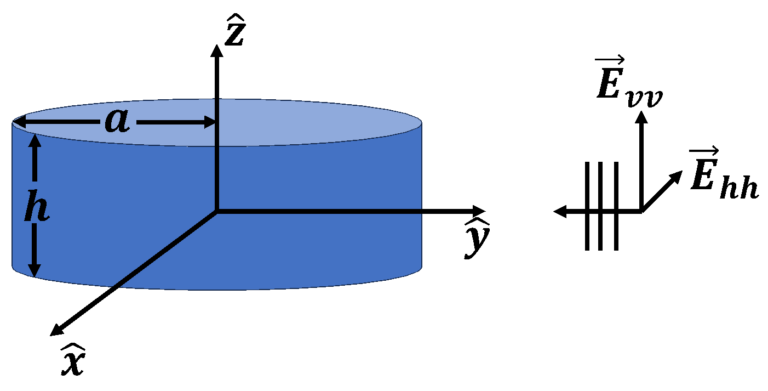
Our final Nyquist example presents a linear field probe which must sample the incident field of a compact range to identify stray signals in the quiet zone to a maximum incident angle of ±90 degrees. A linear field probe sampling the quiet zone incident field in a compact range is shown in Figure 4.
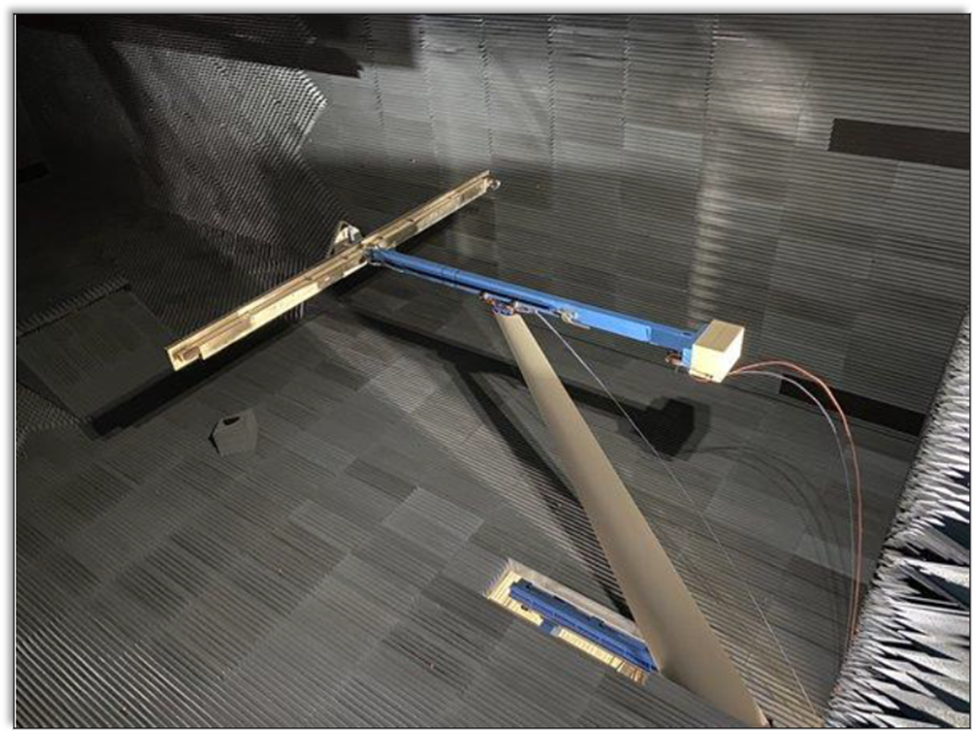
Beginning with the modified point source expression of the stepped angular measurement, we have
$$\sigma=e^{-j\beta dsin\theta}$$
where d is the linear field probe sample position and θ is the incident angle measured from the plane wave traveling perpendicular to the probe axis. Note that this is a one-way measurement which suppresses the factor of two in the phase exponent. The differential phase based on successive probe measurements is
$$\phi=\beta d\sin\theta$$
$$\phi_1=\beta d_1sin\theta,\phi_2=\beta d_2sin\theta$$
$$\Delta\phi=2\pi(\Delta d/\lambda)\sin\theta$$
$$2\pi(\Delta d/\lambda)\sin\theta<\pi$$
Since the maximum bistatic error angle is 90 degrees, the Nyquist sampling criteria here is described by
$$\Delta d<\lambda/2.$$
For a linear field probe to properly sample bistatic error sources at 12 GHz at angles up to 90 degrees from the incident plane wave, the linear probe must move in increments of less than 0.5 inches.