Part I: The Sphere
RCS measurement ranges typically come in two flavors: Research and Development (R&D) and Quality Control (QC). QC ranges are usually an extension of a production line, repeatedly measuring the backscatter (not necessarily far-field RCS) of similar targets, answering the question, “Does it pass?” Operators of QC ranges do not have to be skilled in the interpretation of scattering data but must know how to properly measure their specific target according to a well-defined test plan and know when deviations occur. QC ranges find their maximum usefulness in repeatability from one test to another and are often designed with a specific target in mind.
R&D ranges are usually an extension of a product development program, measuring the far-field RCS, often iteratively, answering the question, “What’s the actual signature and what does it mean?” Operators of R&D ranges are often called to interpret the sources or ramifications of scattering data and must be able to properly measure their target according to a test plan that often changes in real-time. R&D ranges find their maximum usefulness in providing accurate RCS data across multiple frequency bands, azimuth, and elevation apertures, over a wide dynamic range, and able to support a wide variety of target geometries.
As signature levels push lower, there is a corresponding need for operators to better understand scattering behavior, range health metrics, and measurement tradecraft. This article is the first in a series of five where we describe perfect electric conductor (PEC) targets whose scattering features support these three requirements. While there are many targets that can provide helpful insights, these six have important features that are worth discussing:
- Sphere
- Squat Cylinder
- Squat Dihedral
- Ogive
- Conesphere
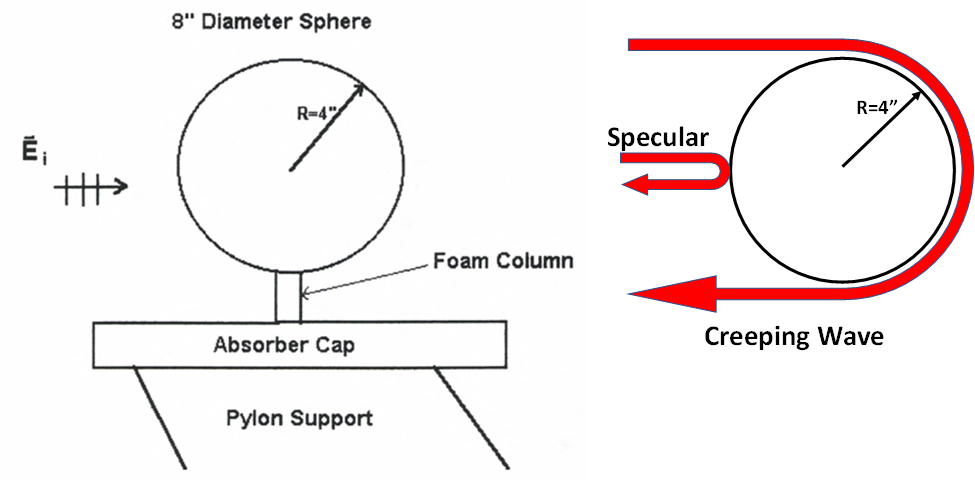
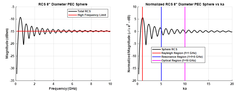
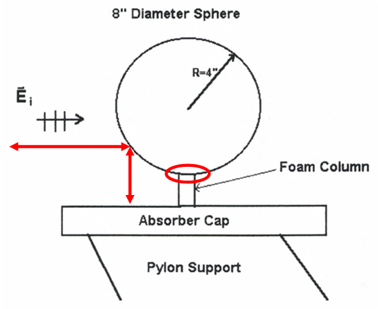
The PEC sphere is the most common and often the very first target measured by RCS range operators. The ability to mount the sphere on almost any foam column, its straightforward scattering features, and easy-to-implement RCS predictions, make the PEC sphere a great way to begin making RCS measurements. A typical sphere mount configuration is shown in Figure 1 (left). The RCS of a sphere in free space is comprised of the contributions from only two scattering features, a specular term from the front of the sphere and what is referred to as a “creeping wave” which attaches to the surface of the sphere and travels around its circumference, scattering energy as it goes, ultimately radiating back to the illuminating radar. Figure 2 (left) shows the RCS of an 8” sphere as a function of frequency (black line) and the high frequency limit in red. Sphere scattering is usually divided into three frequency bands measured not in Hertz, but in terms of the product ka, where k=2π/λ and “a” is the radius of the sphere. This “electrical dimension” of the sphere provides a convenient way to divide the scattering into three regions, Rayleigh, Resonance, and Optical, as shown in Figure 2 (right). In a general sense, the creeping wave dies out as ka becomes large, leaving only the optical region σ=πa^2 term. In the mid-region between 1<ka<5, the optical and creeping wave terms move in-and-out of phase with each other, creating the oscillating pattern seen in Figure 2.
Since the sphere provides such a well-behaved scattering profile across a large bandwidth and is easy to mount on small low density foam columns, it is often the target of choice for measurement calibration. Calibration accounts for the measurement system frequency response and is expressed as
$$\sigma_{cal}=\frac{T_{measured}}{C_{measured}}C_{theory}$$
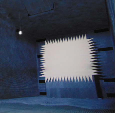
where σcal is the calibrated RCS, Tmeasured is the measured scattered field of the target of interest, Cmeasured is the measured scattered field of the calibration target, and Ctheory is the theoretical RCS of the calibration target. In the case of the PEC sphere, the theoretical solution is readily available by means of the Mie Series. The quality of the calibration depends on the exclusivity of the sphere’s two scattered field components. However, the sphere’s simplistic geometry also makes it susceptible to measurement errors as shown in Figure 3. Here there are two primary sources of measurement error: secondary scattering between the sphere and the mounting structure below and mutual coupling between the Styrofoam support and the surface of the sphere. The secondary scattering strongly illuminates the structure underneath the sphere, causing a significant interfering signal that varies with frequency. The mutual coupling error occurs at the sphere-foam interface where the non-air boundary condition perturbs the creeping wave term. Both errors can substantially degrade the quality of an RCS measurement. To minimize the impact of these errors, operators increase the height of the foam column, thereby increasing the length that the stray signal must travel, shape the absorber cap such that the surface is not directly normal to the stray signal direction of propagation, and finally reduce the footprint of the foam-sphere interface. The combination of these modifications can greatly reduce the impact of these errors. An alternative to these efforts is to hold the sphere from above with low reflectivity strings as shown in Figure 4. The strings, while not invisible to the incident field, present a much cleaner installed configuration, and provides a very accurate RCS response.
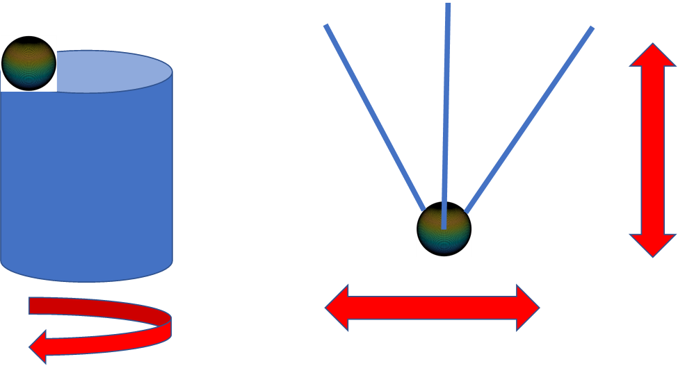
While the sphere has limitations as a calibration target, it can also be used as an effective agent in determining range health. Since the sphere has a constant RCS as a function of angle, the sphere can be used as an effective range two-way field probe. This can be done by placing a sphere on a foam column with a fixed offset from the center of rotation as shown in Figure 5. By rotating the sphere at a fixed frequency, the magnitude and phase of the sphere backscatter will reveal a scaled version of the magnitude and phase of the incident field. The same can be used by traversing the range test zone in a plane to reveal the magnitude and phase of the incident field as shown in Figure 5 (right).
Another measure of range health is the polarization purity of the incident field. In a perfect world, a vertically or horizontally polarized incident field would have no component of the other. This is called cross-polarization purity and is measured in dB. The sphere, as a body of revolution, has no cross-polarization response, thus any measured cross polarization response is caused other elements in the range, such as the reflector feed antenna or the reflector itself.
Conclusion
The PEC sphere, with its limited scattering mechanisms, mounting simplicity, and straightforward computation, make it a powerful teaching tool for range operators and measuring the purity of the incident field. However, its simplicity makes it susceptible to measurement errors. The next article will present the squat cylinder as a mitigating target that resolves many of the sphere limitations.