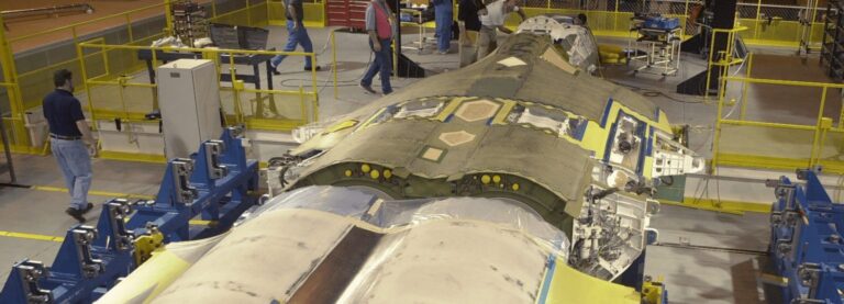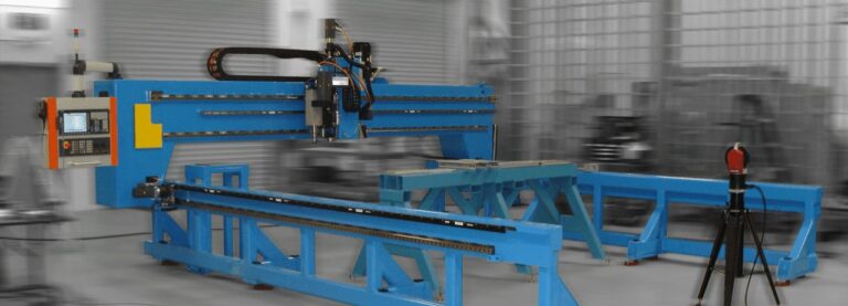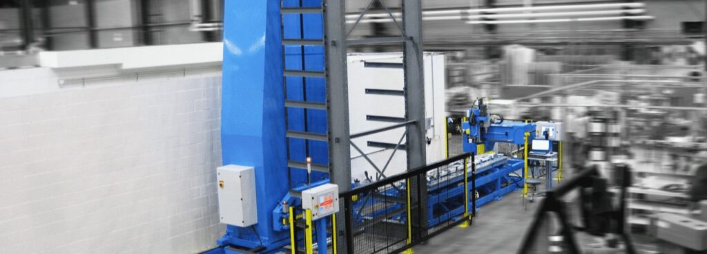
This project reduced the floor space requirements by 70% while improving productivity by 400%. The system drills hundreds of holes in each of 55 variants of bulkheads that are made on 10 variants of jigs. The bulkheads are the primary support structures for the cargo floor of a large Cargo Aircraft. By scanning the barcode on a work order, the system will fetch the correct jig to make that part number bulkhead from the rack and deliver it to the load position where it can be populated with several dozen parts. After loading the parts, the user indicates the parts-loading is complete and the jig is returned to the rack.
On the opposite side of the storage rack is the Auto-drill. When the Auto-drill completes a program, the stacker will pick up the jig and return it to the rack. When the Auto-Drill is empty the system will determine the next jig in the queue and deliver it to the Auto-drill. Drilling is done in 3 passes because temporary fasteners must be moved between pass one and two, and parts are added between passes two and three.
The jigs are moved between the Load Table, Rack, and Auto-Drill all automatically. The queue can be reprioritized at any time and can run for many hours totally unassisted by a human.
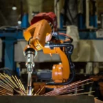
When preparing for pass one, the Auto-Drill will pick a machine vision camera in the spindle and goes to all places where a pilot hole exists in the parts and creates an X-Y offset for every hole with a pilot. This greatly reduces cutter breakage. After creating the offset file, the system puts away the camera and picks up the first cutter to start work. The Auto-Drill has a 10-place tool holder for automatic tool changes.
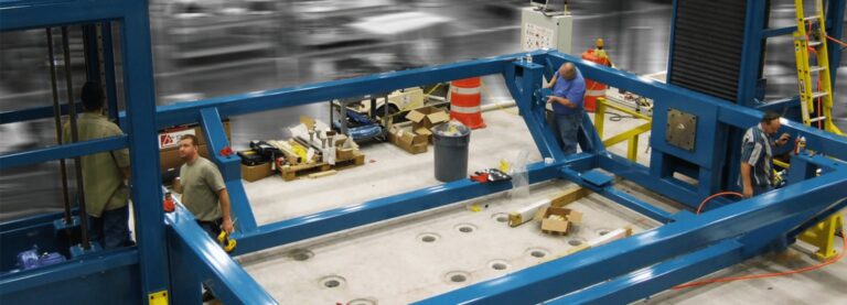
In the pictures shown, the first was taken during the installation before any of the jigs were placed in the Rack. The gray Rack holds 10 jigs – all different. The second picture (below) shows the Stacker frame as it was being assembled at Delta Sigma.
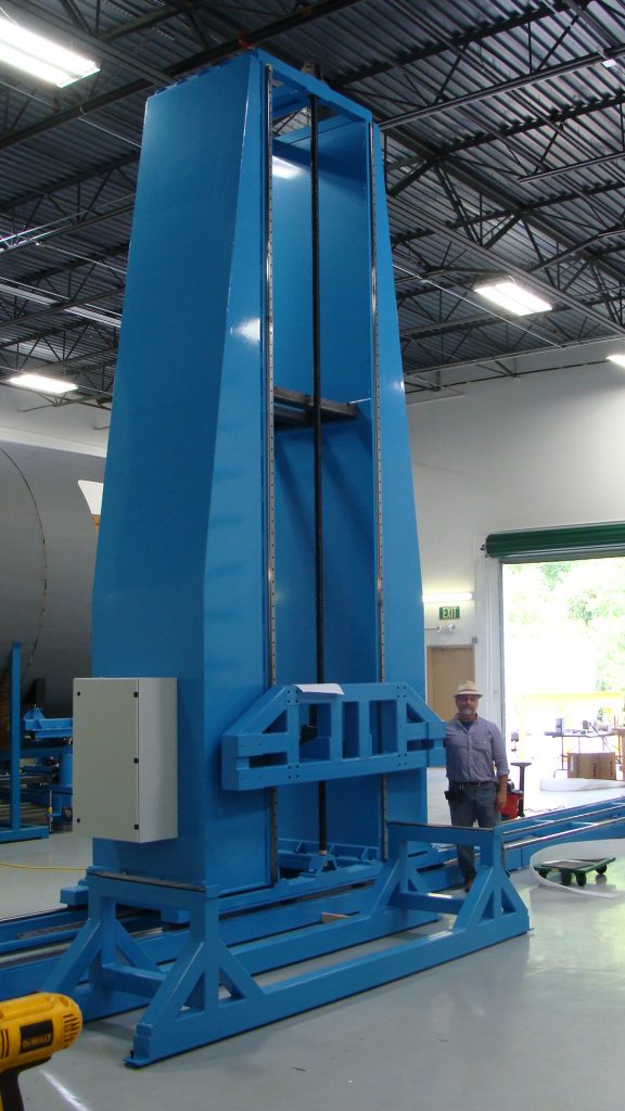
Once a Jig is delivered to the Load Table, two buttons on the user screen will become selectable. When the operator has finished working, they will select either Bulkhead Complete or select RTN Bulkhead Incomplete. In the former case, the Jig will be returned to the storage rack and will be marked Ready to Drill and will indicate the part number that is loaded in that Jig. In the latter case – typically caused by a parts shortage or damaged part – the Jig will be returned to the rack and marked Partial LOAD and will indicate the part number that is partially loaded in that Jig.
The system contains a database that keeps track of the status of all bulkheads. For example, parts can be removed from the Jig for a particular bulkhead for assembly prior to adding the last set of parts. While that bulkhead is away, another set of parts (new serial/tail number) is loaded into that same Jig for drilling all of the holes except the Cleco holes. When the first part returns, the system knows that it only needs to drill the Last Part holes. Status screens will show any incomplete bulkheads that are not currently in the system. Bulkheads can be removed and returned at any time without losing track of their individual status.
STACKER USER SCREEN DESCRIPTION
In the center of the screen is a column that represents the vertical storage rack, showing what is in each position. The options are:
- Ready to POPULATE: This indicates that the Jig is empty and ready to receive parts to make a bulkhead assembly (these are displays only and are not selectable since each jig can make multiple part numbers, the operator will select the part number to be made – not the Jig.)
- Loading xxxxxx: This indicates that the Jig is not in the rack, but rather in the staging area being loaded with new parts. Selecting will move the Jig from the staging area to the rack and will then mark the Jig Ready (or partially Ready) to Drill. The part number being loaded is also indicated. The operator will be prompted for complete or incomplete.
- Ready to DRILL (1) xxxxxx: This shows the Jig is fully populated with parts (minus Last Parts) and the part number is indicated, and it is ready for drill-pass #1, which indicates that Cleco’s are installed. Selecting will move the Jig from the rack to the drilling area and will initiate the drilling operations. When drilling is complete, the stacker will return the Jig to the rack. If the drill system is not ready to receive a new Jig, it will be added to the queue.
- Drill Pass (1) Complete xxxxx: This shows that all of the holes except the Cleco and Last Parts holes have been drilled. Selecting will move the Jig from the rack to the staging area where the technician will remove the Cleco’s and install full size Cleco’s needed to hold the parts in place during the next drilling operation.
- Ready to DRILL (2) xxxxxx: This shows the Jig is fully populated with parts (minus Last Parts) and the part number is indicated, and it is ready for drill-pass #2, which indicates that initial Cleco’s been removed and new Cleco’s are installed. Selecting will move the Jig from the rack to the drilling area and will initiate the drilling operations. When drilling is complete, the stacker will return the Jig to the rack. If the drill system is not ready to receive a new Jig, it will be added to the queue.
- Drill Pass (2) Complete xxxxx: This shows that all the holes except Last Parts holes have been drilled. Selecting will move the Jig from the rack to the staging area where the technician will remove parts to destack/deburr and then move to the staging rack where rivets are installed, then to the holding fixture where lockbolts are installed, at which point it is ready to return to the drill system for Last Parts drilling.
- Ready to DRILL (3) xxxxxx: This shows the Jig is fully populated with parts and the part number is indicated, and it is ready for drill-pass #3, which indicates that the Last Parts are to be drilled. Selecting will move the Jig from the rack to the drilling area and will initiate the drilling operations. When drilling is complete, the stacker will return the Jig to the rack. If the drill system is not ready to receive a new Jig, it will be added to the queue.
- Drill Pass (3) Complete xxxxx: This shows that all the Last Parts holes have been drilled. Selecting will move the Jig from the rack to the staging area where the technician will remove assembly from the Jig. At this point the bulkhead is complete and is out of the system – no longer being tracked.
- Partial LOAD: This shows the Jig is partly populated with parts and the part number is indicated. Selecting will move the Jig from the rack to the staging area so that loading can be completed.
- DRILLING (x) xxxxxx: This indicates that this jig is not in the rack at all, but is currently moving-to, in, or moving-from the drill area. This is a display only, not selectable. The number in the (x) indicates which drill pass is currently executing. The system will return the Jig to the rack when drilling is complete without operator prompting.
- Drill Partial xxxxxx: This indicates that the Jig in this rack position has had drilling initiated but was for some reason discontinued before the drill program was completed. Selecting will move the Jig from the rack to the drilling area and the program will begin to execute starting from the next hole after the last one drilled. The system will not lose track of the proper starting place through power-downs.
- Ready to DeStack xxxxxx: This indicates that the items in this Jig are fully drilled and ready to be removed from the Jig. Selecting will move the Jig from the rack to the staging area where the technician will remove the drilled parts.
- DeStacking xxxxxx: This indicates that the Jig is not in the rack but is in the staging area having the drilled parts removed. Selecting will move the Jig from the staging area to the rack and will the mark the Jig Ready to Populate.
The workflow is very intuitive and the system makes most of the decisions – what Jig to use, which holes to drill and where, plus provide convenient storage for Jigs at any stage of readiness automatically tracked (and indicated) regarding their current state of assembly.
This concept of keeping track of many similar but different assemblies required for one system – in this case over two dozen bulkheads per aircraft, all unique – can be applied to all kinds of applications. Automated tooling makes complex things become simple, or at least simpler.