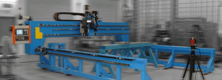
This project was to develop and build a wireless measurement technique to measure the total variance of the mate surface of the wing of a large Cargo aircraft and 3-axis (of which 2 axes are linear and one is polar) milling machine that is very small and easily portable that will remove all the variance from the four corner fittings. After the measurements are taken, the cutting tool is attached to the holding fixture and turned on. The system does not require anything of the operator – it knows how to make the cut to the proper depth exclusively from the GripGage data. Cut time is typically 5-10 minutes and does not require any operator intervention during that time. Trading off minimizing size and weight while maximizing speed and accuracy was a key part of the design challenge.
The MiniMill’s Ingenious Design
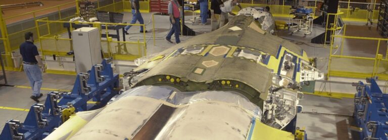
The wing uses an ingenious design where all the manufacturing tolerances are accumulated to the mating surface that is made sacrificially thick. Measurements of each of the wing nodes to a reference plane are made to determine the optimal material removal of all the wing nodes to achieve the lightest weight yet strongest fitting that will provide a perfectly planar surface for the mate, perpendicular to the airflow. These measurements and the calculations to determine the cut depth were automated from the manual method used previously.
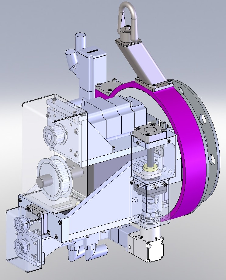
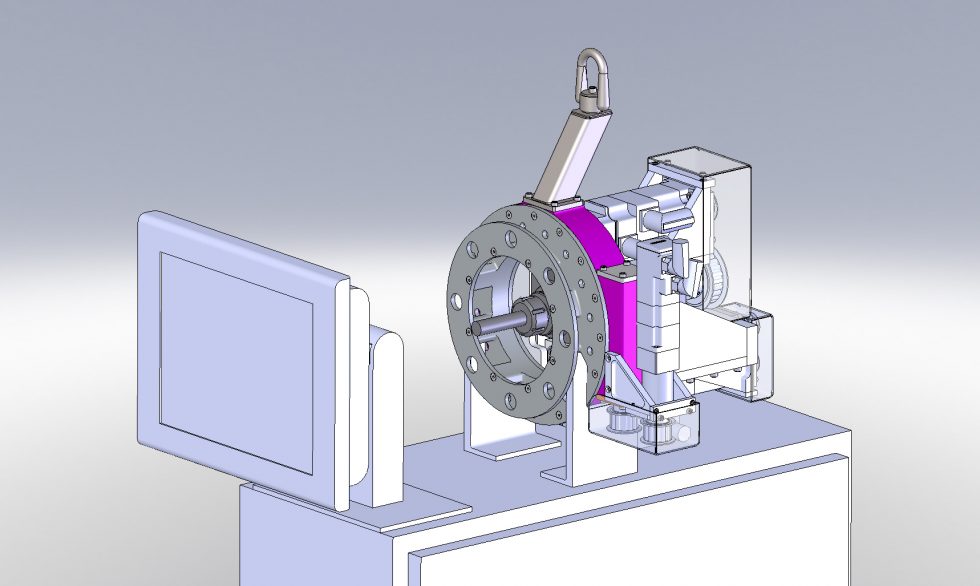
The system consists of a controller cabinet that house all the motion control system. The MiniMill resides in a cradle on top of it when not in use. A cable connects the controller to the MiniMill. The MiniMill weighs about 100 pounds and includes a balancer to help put it in place.
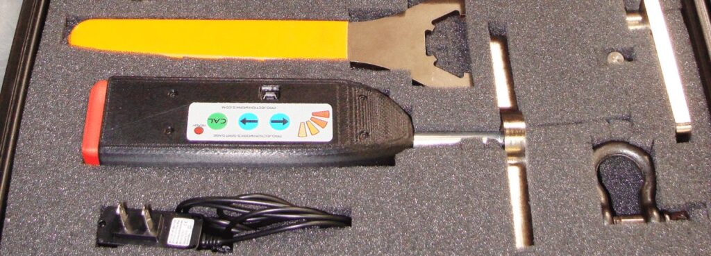
Delta Sigma developed and patented an automated method to measure hole depths and gaps very accurately and very rapidly. The device is called a GripGage and comes in several varieties. Primarily there are wired/wireless and plunge/retract. This system used the wireless plunge type GripGage. This application was not the intended purpose of the GripGage, so modifications were required and well as a new software interface to use the measured values in a new way. The electronics and measurement mechanics were unchanged from the standard design, but the part that touches the holding fixture and the part that touches the Wing Nodes were a special design specifically for this purpose.
The data acquisition mechanics and firmware were all standard COTS products of Delta Sigma. However, the use of the GripGage in this application is unique; and thus, requires an application program to be written into the device controller that is specifically for this purpose.
Effectively Utilizing The MiniMill
For the measurement system to be useful, the raw measurements had to be transferred into the controller where they were processed to optimize the best fit for cutting the nodes into a common plane. The data transfer is automatic and is “invisible” to the operator; that is, it happens without any special action on the part of the user. The user interface has a common look and feel between the Center and Outer Wing areas, but the specifics of the GUI are a bit different to accommodate the differences in their respective methods of operation. Measurement data is stored and accessible for trend analysis.
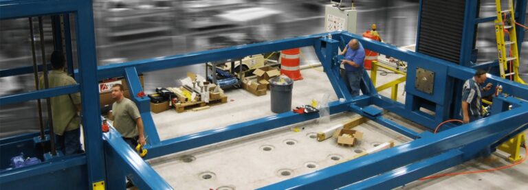
This milling machine is a built-for-purpose system. A hoist loop on the top of the Mill allows a balancer to pick the unit up so the user is holding a pound or so when aligning it to the holding fixture that supports the wing. The mounting face attaches to the holding fixture where it is held in place by alignment pins and a bolt.
The measurements made by the depth gage have been wirelessly transmitted to the MiniMill controller via a Zigby AES128 encrypted data link. A Delta Sigma proprietary algorithm in the controller analyzes the measurements and determines the proper cut depth to create a fully optimized plane that will be perpendicular to the airflow over the wing, cuts the shallowest node by at least 0.005 inches, and ensures the highest node will not be cut greater than an acceptable amount. The MiniMill cuts the master corner of the wing which sets the reference for the remaining wing nodes. Once the four corners of the wing mating surface are cut to the correct plane, the wing is removed from the jig and moved to a lay-down fixture where the WingMill cuts the remaining nodes to that plane.

