Ensuring Correct Alignment Of Air Force C-5M Pylons
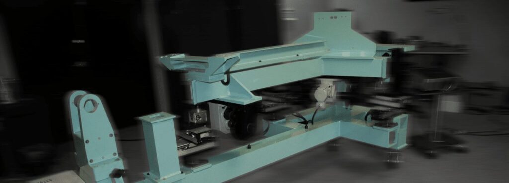
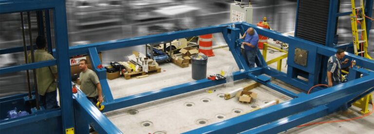
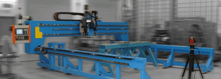
When Lockheed Martin was selected to upgrade the US Air Force’s C-5 Galaxy fleet, Delta Sigma Company was asked to develop an automated alignment positioning tool to ensure the correct alignment of the new stronger engine pylons that were included with the C-5M design.
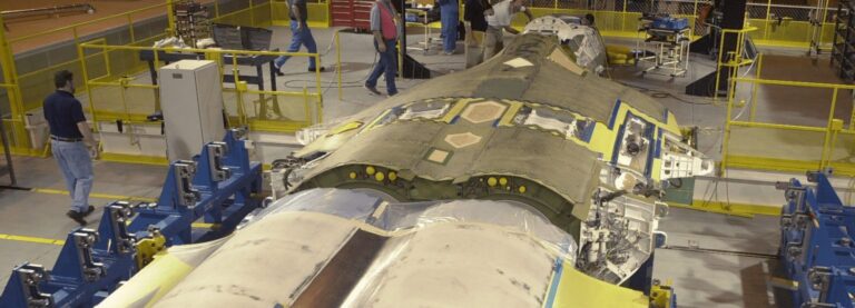
The solution developed by Delta Sigma utilized a machine vision-based system similar to the alignment system developed for the F-22 Raptor fuselage mate project. As you can probably imagine, when you have four very powerful jet engines attached to the bottom of your wing, it is highly advantageous to have all four of them pointing in exactly the same direction. When you are replacing the engine pylons on 40-year-old aircraft with newer, bigger, and much stronger engine pylons the challenges in achieving the ideal alignment are numerous and complex.
Removing the old pylon lugs leaves the wing full of holes in very high-stress locations where you do not want any unnecessary holes. That is followed by replacing the lugs with newly designed pylon lugs that cover a larger area, maximize the use of all pre-existing holes, and ultimately allow us to end up with four sets of pylon lugs that are perfectly aligned so that when the engine mate occurs, all engines will be properly oriented.
How To Make Multi-Dimensional, Multi-Location Alignments
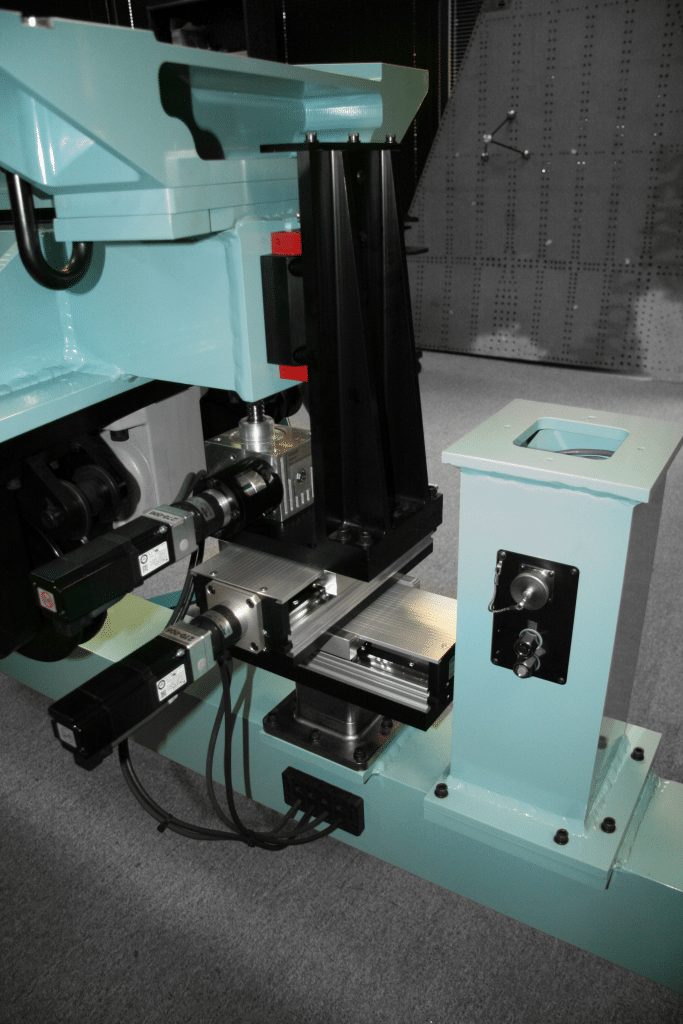
Delta Sigma Company used the vision-pin design which was originally developed to assemble the F-22 fuselage on the full-rate production line in Marietta, Georgia. Anyone who has ever attempted to make multidimensional, multi-location alignments so that a large rigid alignment pin will insert into a clevis, is well familiar with the pain periodically associated with getting a pin back out when the fixture was moved slightly in another location after a pin was inserted. Delta Sigma’s vision-pin design eliminates this problem.
Conceptually, understanding the vision-pin technique is simple. Using a light beam as our “alignment pin” has the very advantageous benefit that we can have a zero-tolerance fit of that “alignment pin” while concurrently having a zero percent chance our “alignment pin” will get stuck. Once ALL positions that need alignment are in perfect alignment as measured by the vision pins, simply remove the vision pins and replace them with steel pins to hold the body rigid, which now easily slide in and out. Or, perhaps run a boring tool to open the hole to full-size once perfect alignment is achieved.
This technique works well for wing boring in addition to engine pylon mates. It is a fairly common practice to perform a process (i.e. cutting) that is going to put some significant forces into an assembly that must remain very stable throughout that process. Prior to the process, a complex alignment process (often manual measurements with manual adjustments) that ends by inserting large steel pins is employed. Delta Sigma’s integrated contactless measurement system and servo actuation system together eliminate that manual process and can reduce mate time by up to 99% on a complex mate.
Publications
Charles Masi wrote the cover story for the April 2009 issue of Vision Systems Design magazine, which features the Delta Sigma Automated Pylon Lug Alignment System that was incorporated into Lockheed Martin’s C-5M production line. A total of 16 tools in all were built: left wing inner and outer engines, and the mirror of those tools on the right; and tools for 4 stations were built. You can read that story here: https://www.vision-systems.com/non-factory/defense-aerospace/article/16747927/engine-of-flight
The C-5 is an engineering marvel. It amazes me, even today, that someone thought they could do that. Here is the USAF fact sheet on the C-5M Super galaxy: https://www.af.mil/About-Us/Fact-Sheets/Display/Article/104492/c-5-abc-galaxy-c-5m-super-galaxy/
The link below shows a couple of takeoffs of the C-5M Super Galaxy. In the second takeoff you can see liftoff is only 4 or so body lengths of the aircraft and the incredible angle of ascent. The power of those engines – over 200,000 pounds of thrust – is being transmitted through the engine pylons and through the pylon lugs discussed in this blog to lift 840,000 and travel at up 518 mph.

