Precision Alignment Using Machine Vision
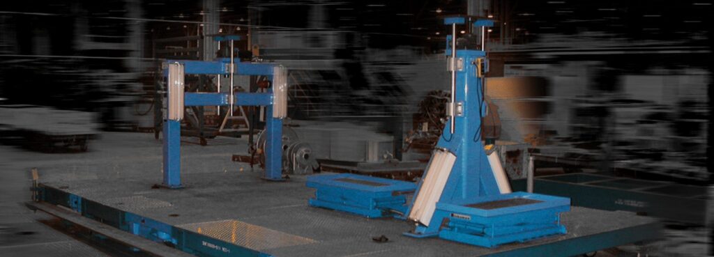
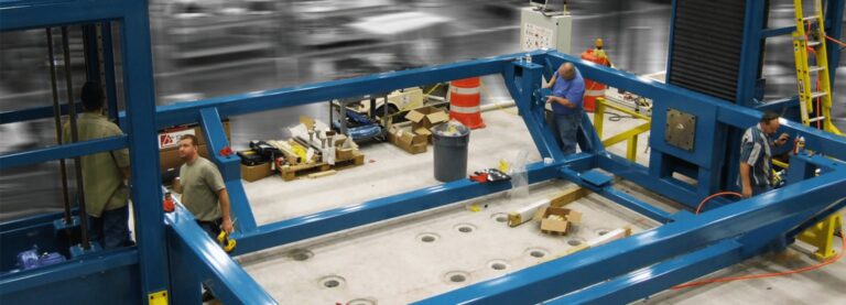
Delta Sigma Company developed a machine vision-based system to align the fuselage sections of the F-22 on the Final Assembly Line (FAL) in Marietta, GA. The alignment of the sections for the fuselage mate has a very high tolerance. The total system consists of five sets of three “skates” each – one for the forward, mid, and aft fuselage sections. The machine vision system provides contactless measurements very fast and very accurately. This is a 96-axis servo-driven system.
How To Make Multi-Dimensional, Multi-Location Alignments
Delta Sigma Company used the vision-pin design which was originally developed to assemble the F-22 fuselage on the full-rate production line in Marietta, Georgia. Anyone who has ever attempted to make multidimensional, multi-location alignments so that a large rigid alignment pin will insert into a clevis, is well familiar with the pain periodically associated with getting a pin back out when the fixture was moved slightly in another location after a pin was inserted. Delta Sigma’s vision-pin design eliminates this problem.
Conceptually, understanding the vision-pin technique is simple. Using a light beam as our “alignment pin” has the very advantageous benefit that we can have a zero-tolerance fit of that “alignment pin” while concurrently having a zero percent chance our “alignment pin” will get stuck. Once ALL positions that need alignment are in perfect alignment as measured by the vision pins, simply remove the vision pins and replace them with steel pins to hold the body rigid, which now easily slide in and out. Or, perhaps run a boring tool to open the hole to full-size once perfect alignment is achieved.
This technique works well for wing boring in addition to engine pylon mates. It is a fairly common practice to perform a process (i.e. cutting) that is going to put some significant forces into an assembly that must remain very stable throughout that process. Prior to the process, a complex alignment process (often manual measurements with manual adjustments) that ends by inserting large steel pins is employed. Delta Sigma’s integrated contactless measurement system and servo actuation system together eliminate that manual process and can reduce mate time by up to 99% on a complex mate.
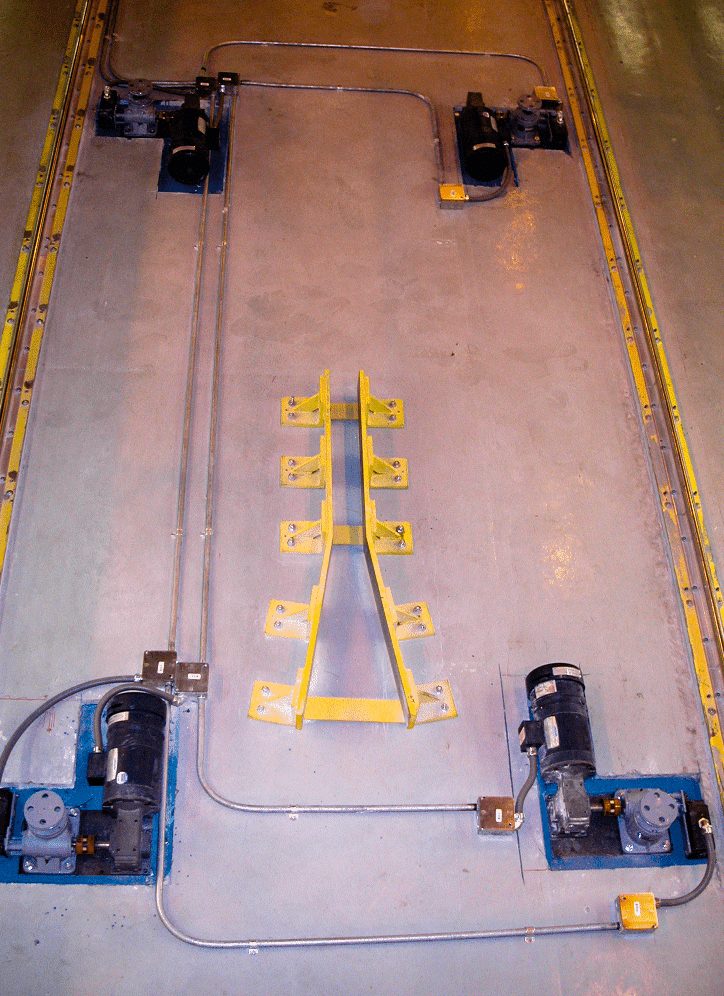
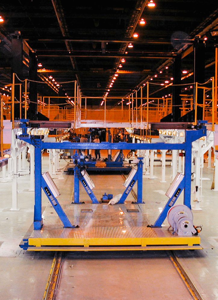
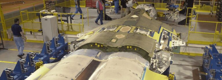
Each Skate is divided into two systems that each have their own control system. The most critical part of the system is aligning and mating the mid and aft fuselage sections which arrive at Marietta from Lockheed Martin in Fort Worth and Boeing in Everett, respectively. The wings cross this joint and it thus has a very high tolerance. This is a fully automated machine vision/servo-actuated system called the Mid-Aft Mate Alignment System (MAMAS). The MAMAS system rides atop the manually driven platforms that are used to drive freely on the aisleways from the end of the production line back to the beginning, or in a highly constrained way to drive from station to station on the assembly line with the fuselage at various stages of a partial mate. This system is called the Progressive Assembly Platform Automation System (PAPAS).
Progressive Assembly Platform Automation System (PAPAS)
Jacks at each end of the line allow the user to transition the Skate from “freewheeling” to being forced into following a straight line (within 0.005” across 278 feet of length). The PAPAS allow the Skates to move between stations with only part of the interference-fit holes drilled, without concern about losing position. The PAPAS moves the fuselage sections together so they are close enough for the MAMAS to operate.
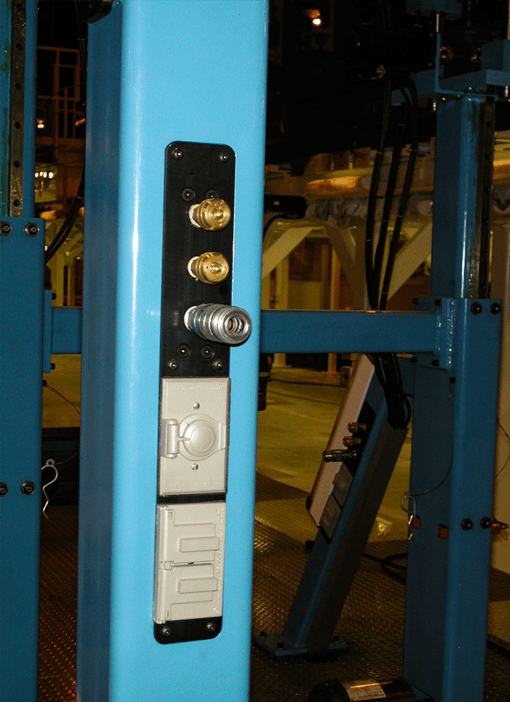
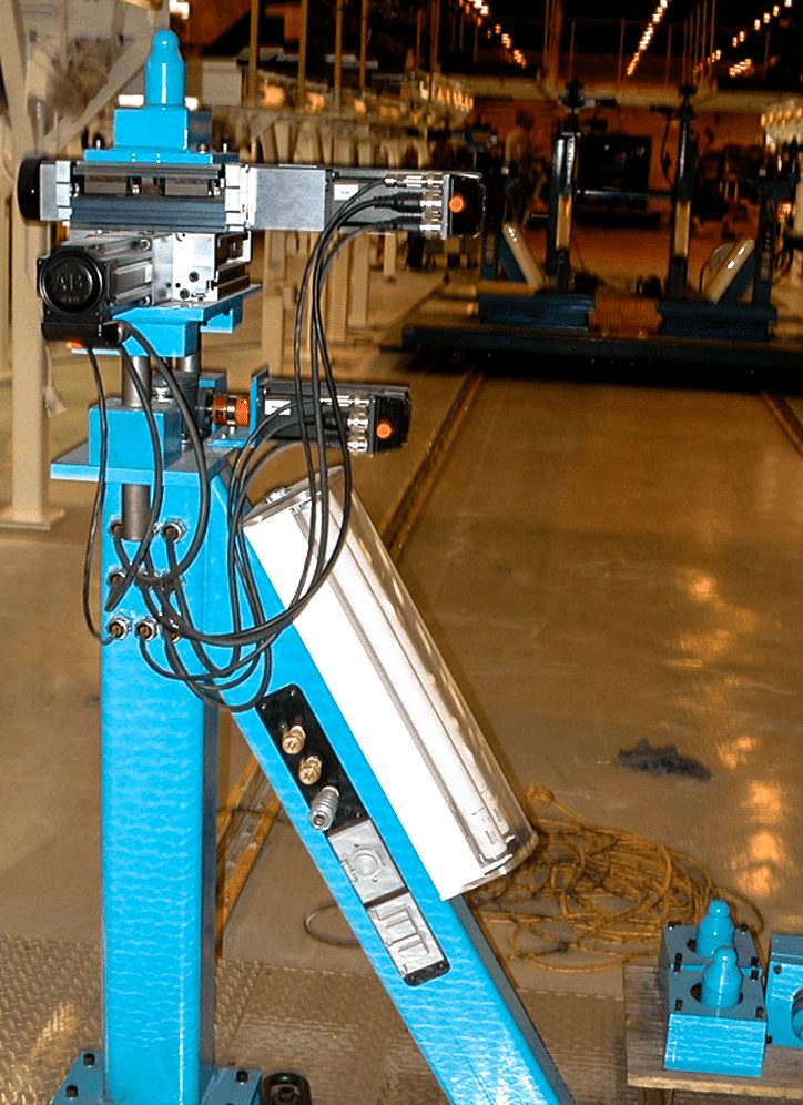
The Skates have built-in scissors lifts, under-belly lights with polycarbonate covers, 110V and 208V/3 phase electrical power, and pneumatic power with two hose diameters all built-in throughout each Skate. When on its casters, the PAPAS can turn on its own center or any radius desired. The PAPAS system is battery-powered with a charging station built in at one of the work cells. The system was designed to make 5 laps around the assembly line on a single charge.
Mid-Aft Mate Alignment System (MAMAS)
Creating the mate joint with very high precision is critical. An alignment of the large fuselage sections is required first, and then the mid and aft are slid together as a stovepipe fitting. The multi-dimensional jacks at the hard-points of each fuselage section support the aircraft sections and move them as needed in 6 degrees of freedom.
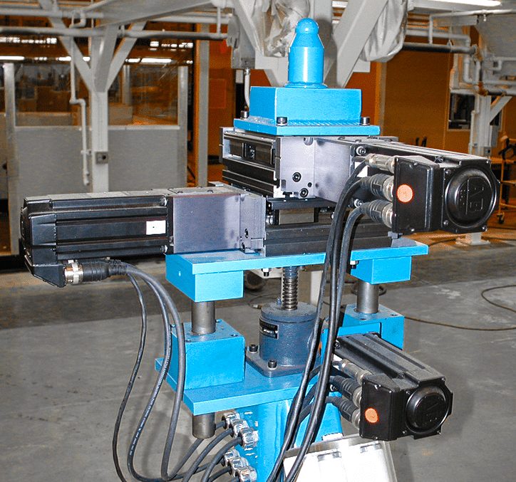
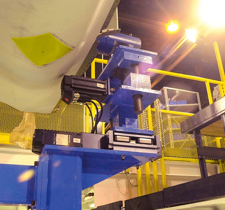
The machine vision system can measure the alignment of the mid and aft sections with respect to a tooling fixture that represents “a perfect wing”. If all the fuselage lugs are aligned with their wing lugs, then the fuselage sections are attached together while everything is held rigid for several weeks and station-to-station moves, the wings will attach with no reaming or boring. The entire F-22 production run was made without a single wing requiring any special action to bolt on. Any right-hand wing fits on the right side of any F-22 fuselage, as do the lefts.
A machine vision camera called a “vision pin” is mounted inside a precision housing and a calibration method was devised to determine the precise center of the image sensor. On an opposite-facing clevis, a precision bored face of a “light pin” is exposed to the camera. These two items essentially create a virtual alignment pin that is made of a light beam. It is extremely accurate and as it is made exclusively of photons, it never gets stuck while trying to make a complex alignment and mate.
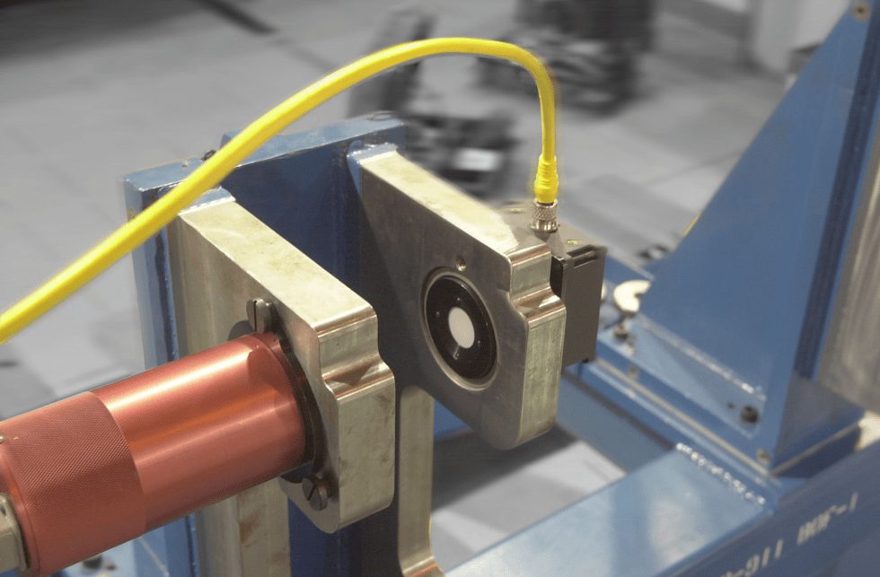
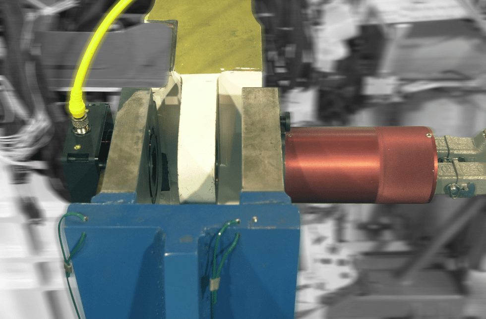
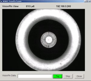
When the wing lug is between the two halves of the “pin”, the camera can measure the position of the wing lug relative to the light pin. An algorithm developed by Delta Sigma then computes how to move 7 axes such that the fore and aft part of each fuselage module is adjusted in six degrees of freedom concurrently to arrive at the proper alignment. This alignment occurs before the sections are mated. The camera’s traverse axes (water and butt) are measured by the camera to an accuracy of 0.0001 inches and the in-line axis (station) has an accuracy of 0.001 inches. The user can view any of the eight Vision Pin views but typically does not need to do so.
It is essential to note the system is not a simple closed-loop tracking system with each vision pin independently attempting to achieve an independent goal. Three-dimensional measurements are being made in 4 places on each fuselage module. Three-dimensional motion is induced in 4 other places on each fuselage module. The motion induced from any position affects the measurements in all axes at all positions. Conversely, achieving a three-dimensional alignment at any one measurement position requires movement at all the hard-point positions. The system works because the calculations to induce precisely the right motion to solve for 22 measurements using 7 axes of control on each module at each position determines how much and in what direction to move each motor before any movement takes place.
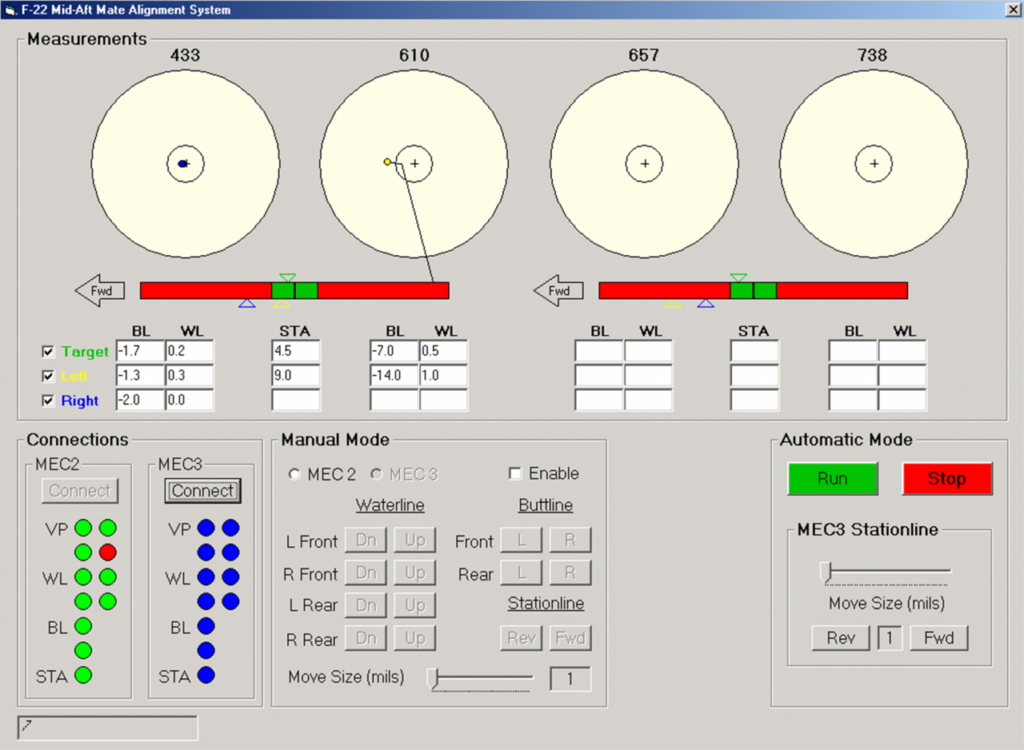
The user screen allows the user to quickly see and understand the state of alignment at a glance. There are four stations where Vision Pins are located, in each case – one left side and one right side. Each circle represents a station and the colored “balls” represent the two sides. The green balls in the alignment circles represent the average of the misalignments between the two sides. On the lower left of the screen are the status indicators of the Vision Pins and each of the servo axes. If one is red, the system will not operate, and clicking the red indicator will inform the operator of the details of the fault.
When the left and right balls are within the outer circle, the MAMAS system is close enough to make accurate measurements. Selecting “RUN” causes the alignment. When the balls are within the inner circle, the water and butt alignment is within tolerance. The station alignment is shown on the bar below the circles.
Publications
Vision System Design
https://www.vision-systems.com/home/article/16737418/visionguided-system-speeds-fa22-assembly
EDN
https://www.edn.com/taking-flight/

