What is a plane wave?
Plane waves are an indispensable facet of RF measurements, theory, and analysis. A plane wave is an electromagnetic (EM) wave that travels with constant amplitude and phase in all directions perpendicular to the direction of propagation. Stated another way, it consists of oscillating electric and magnetic fields that are perpendicular to each other and to the direction of propagation. In practical terms, EM waves begin as point sources that travel spherically outward with increasing diameter. Eventually, the wave travels far enough from its source (e.g. antenna) where a cross-section of the expanding sphere surface is flat enough to be adequately described by a plane.
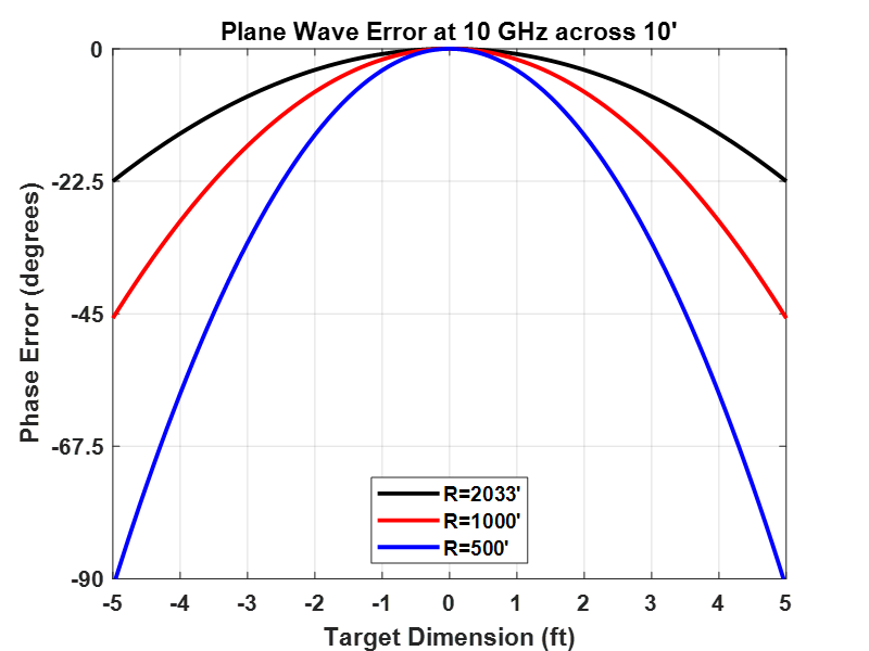
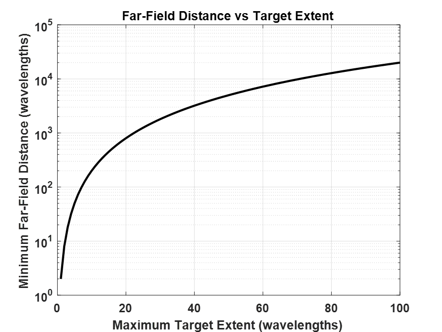
This can be visualized in two dimensions as arc segments of increasing diameter traveling away from a point source as shown in Figure 1. Here, a 10 GHz EM wave spreads outward with arc segments drawn across a 10-foot aperture at distances of 2033’, 1000’, and 500’. The farther away the arc segment is sampled from the source, the closer the segment looks like a line. If this example is extended to three dimensions, the lines become planes. The metric used for wave planarity (by convention) is when the deviation from a perfect plane is 22.5 degrees or less, which corresponds to λ/16, or 22.5 degrees. The expression for this maximum plane wave phase error is defined as R≫2L2/λ, where R is the distance from the EM source and the target, L is maximum target extent perpendicular to the direction of plane wave travel, and λ is the operating wavelength. This analytical expression is also referred to as the “far-field criteria.” Two other distance metrics which must be met to satisfy the far-field criteria are R≫L and R≫λ. A more generalized presentation of the far-field criteria is to express the target extent L in terms of wavelengths which is shown in Figure 2.
Why the need for a plane wave?
Radar Cross Section (RCS) is defined as
$$\sigma=\underset{R\rightarrow\infty}{4\pi R^2}{\lbrack\frac{E_s}{E_i}\rbrack}^2$$
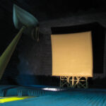
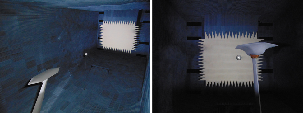
where σ is the RCS in units of square meters, R is the range from the EM source to the target, Ei and Es are the magnitudes of the incident and scattered fields respectively at distance R. Since RCS is defined in the limit as range approaches infinity (R→∞), the far-field criteria is an approximation based on an acceptable deviation from the perfect plane wave, ensuring that the whole target is equally illuminated at the same time. As the incident field deviates from a plane wave, the measured RCS becomes corrupted from the true RCS. The dilemma facing RCS measurement practitioners is that the far-field criteria becomes intractable for practically-sized targets, placing unrealistic demands on the distance between the EM source and its target, as shown in the example of Figure 1. Since there are very few measurement ranges with 2000’ of unobstructed measurement distance, the compact range was devised to meet the far-field criteria in a “compact” amount of real estate or “range.” One example of a compact range is shown in Figure 3. Here the target of interest is the DSC Enigma low observable test fixture with a calibration sphere placed in front. The serrated shape in the background is the compact range reflector which transforms the spherical wave sourced at the focus into a plane wave.
How do I generate a plane wave in a compact range?
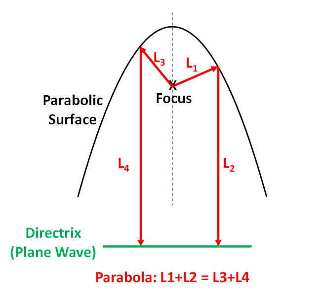
Given that RCS is defined in the limit as R→∞, the purpose of a compact range is to “Capture Infinity in a Box.”[1] To that end, the compact range employs a plane wave transformer or lens to convert the spreading spherical EM wave to a plane wave. This conversion takes place most often through the use of an parabolic reflector. The definition of a parabola makes it a natural choice for spherical-to-plane wave conversion as shown in Figure 4. Here, a parabolic surface is illuminated by a spherical EM wave, usually by an antenna, from the focus. The total path length between the focus, the parabolic surface, and the directrix are the same, regardless of the where the incident field intersects with the parabolic surface. The directrix in this example which indicates a common path length for all rays emanating from the focus, indicates the presence of a plane wave, thus satisfying the far-field criteria. From another perspective, once can say that parallel rays incident on the parabolic surface all converge to the focus.
[1] The phrase, “Capture Infinity in a Box,” was first proposed by Hirsch Chizever, formerly of Mission Research Corporation, in 1994. The phrase became the mission statement for the Advanced Compact Range at Wright Patterson Air Force Base and was inscribed in Latin on the range emblem as, “Captus Infinitum Arcam.”
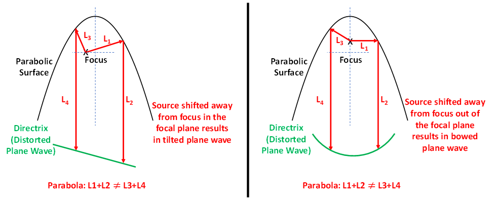
When a source is displaced from the focus, the plane wave is distorted according to that shown in Figure 5. When the source is displaced from the focus within the focal plane, the plane wave is distorted, signified by a tilted phase front. When the source is displaced from the focus outside of the focal plane, the plane wave is distorted, signified by a bowed phase front.
How do I measure the quality of a plane wave in a compact range?
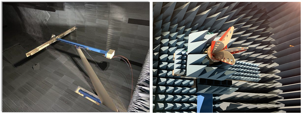
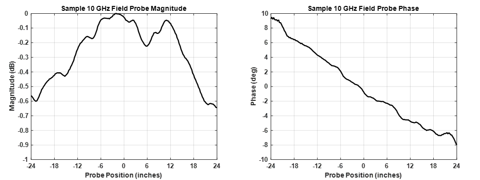
The need to accurately locate the compact range reflector parabola is paramount in the pursuit of plane wave purity. RCS and antenna measurement practitioners go to great lengths to place the range feed source at the focus of the parabola. This is an arduous iterative process, as source antennas often have phase centers that shift along the antenna central axis with frequency, causing a bow to occur within the measured parabola scattered field. Validating a plane wave is performed by use of a field probe in which the parabola scattered field is sampled in amplitude and phase across the intended plane wave dimensions. Two typical field probe configurations are shown in Figure 6. Field probe data are analyzed for a combination of magnitude and phase taper and ripple, two metrics indicating the purity of the plane wave environment. Tapers on the order of 1 dB at the plane wave extent is considered adequate, while phase taper of 22.5 degrees is the maximum deviation permitted as described in the discussion of the far-field criteria. Magnitude ripple about the plane wave taper is a measure of plane wave purity. In a perfect plane wave environment, only electric field taper will be observed. However, in reality, there are more signals entering the plane wave environment than just the desired from the source at the focus. A ripple envelope greater than 1 dB is considered a distorted plane wave and more advanced analysis is required to identify the causes and mitigate them. Sample magnitude and phase field probe presentations are shown in Figure 7.
Conclusion
This article identified the nature and application of plane waves in an RCS measurement context. Antenna performance measurements also rely heavily on the far-field criteria but may also use near-field (close-in) measurements to achieve far-field metrics through a mathematical process. Additional areas of study, include the design and use of compact range reflectors, radar absorbing material selection and placement, instrumentation requirements, and structural concerns.