The use of the Fourier Transform in RF measurements
There are few tools more helpful to RF engineers than the discrete Fourier Transform. Most students learn about the DFT based on sampled time and frequency examples apart from any physics associated with a particular application. However, when the sampled and transformed variables are linked together through physical realities such as bandwidth, time span, angular aperture, distance, and Doppler, the DFT becomes more than an isolated equation that undergraduates learn from a textbook. With a tailored expression of the DFT, and some relationships between the sample and transform variables, even a novice can use the DFT to analyze RF data:
$$V_2(m)=\sum_{k=0}^{N-1}{V_1(k)e}^{-j2\pi v_1v_2}$$
| $$V_1$$ | $$Sampled\;data$$ |
| $$v_1$$ | $$Sampled\;variable$$ |
| $$V_2$$ | $$Transformed\;data$$ |
| $$v_2$$ | $$Transformed\;variable$$ |
| $$v_2\;units$$ | $$\frac1{v_1}\;units$$ |
| $$\overline{v}_2\;span$$ | $$\frac1{\triangle v_1}$$ |
| $$N_{DFT}$$ | $$Next\;power\;of\;2:\;\lbrack\frac{2{\overline v}_1}{\triangle v_1}\rbrack$$ |
| $$Resolution$$ | $$\frac1{\overline{v_1}}\;span$$ |
| $$v_{2\;}axis\;\lbrack Lo:\triangle:Hi\rbrack$$ | $$\lbrack-{\overline v}_2/2:\;{\overline v}_2/N_{DFT}:\;v_2/2-{\overline v}_2/N_{DFT}\rbrack$$ |
In this session, we’ll look at four applications of the DFT in the RF measurement context using the relationships in Table 1.
Discrete Frequency Sampling
The most common measurement performed in antenna and radar cross-section (RCS) chambers is the character of the incident field and backscatter response of antennas and targets. Whether the source is a stepped-CW network analyzer or instrumentation radar, or from a linear chirp, the measured response is almost universally transformed into the time domain through the DFT to isolate the desired response from any other chamber responses.
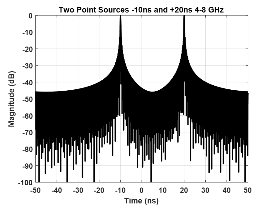
Consider a chamber response dominated by two-point sources of equal magnitude, from 8-12 GHz with 10 MHz sampling. One point source is at -10ns and the other is at +20ns. The 10 MHz spacing provides an unambiguous time response of 1/(0.01 GHz) = 100ns with a resolution of 1/(4 GHz) = 0.25ns. The time response is shown in Figure 1.
Discrete Time Sampling
The DFT transformed units are the reciprocal of sampled units. Sampled time (sec) results in (1/sec), sampled angle (rad) results in (1/rad), sampled distance (m) results in (1/m). In some instances, a standard sampling in time, can be transformed into other units simply by imposing physical constraints based on the scenario.
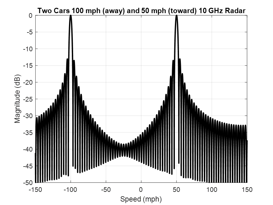
To illustrate this concept, consider a 10 GHz police radar measures the scattered phase from passing traffic every 100μs. Two cars pass the radar, one coming toward the radar at 50 mph while the other goes away from the radar at 100 mph. Using the same principles from Example 1, with appropriate scaling of the transform axis by the wavelength at 10 GHz, the speed of the two vehicles is shown in Figure 2.
Discrete Angular Sampling
It is commonplace in chambers to measure antenna and RCS properties as a function of angle. Sometimes, customers require non-standard data products from standard measurements. This is made possible through proper application of the physics of the configuration applied to the output of the DFT.
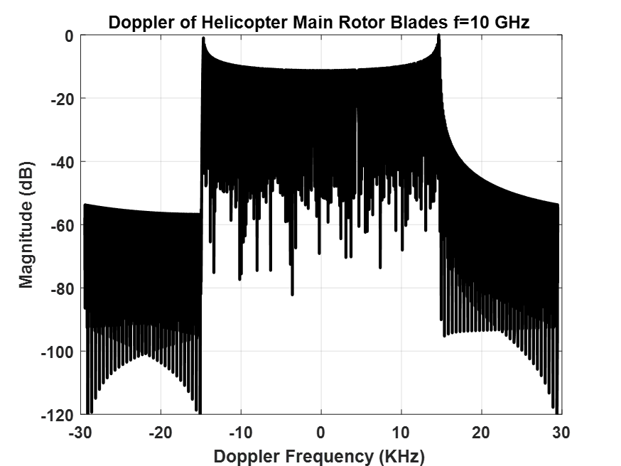
For example, a helicopter manufacturer comes to your range and wants you to measure the Doppler return from the main rotor blades. You obviously can’t operate the helicopter inside the chamber, but you can accurately measure the backscatter of the rotor blades at 10 GHz at discrete angles. With the sampled variable as radians, Fourier Transform properties require the transform variable to be 1/radians, which by itself is not helpful. However, if you know the rotation rate of the main rotor (radians/second), you can scale the transform axis and achieve Doppler information (1/radians x radians/second = Doppler frequency) as shown in Figure 3. As a check, the manufacturer said the tips of the blades have a linear velocity of 221 m/s, which at 10 GHz creates a Doppler frequency of 14.7 KHz, the same frequency reported by the rotor extent in Figure 3.
Discrete Linear Position Sampling
For many ranges, measurements sample over two variables or more simultaneously, such as frequency and distance. This combined response requires application of the DFT in two directions and interpolating the results on to a common grid for both variables. Additionally, the results may be scaled according to the physics of the scenario, resulting in a transformed output of frequency and angle.
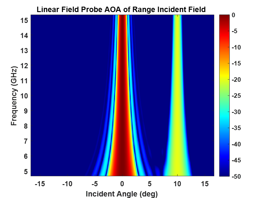
A common scenario is to employ a linear field probe to determine the purity of the incident field over an 8-foot quiet zone from 2-18 GHz. The field probe samples the incident field aperture in steps of 0.25 inches and frequency range in 10 MHz increments. The Fourier Transform is applied in the linear travel direction providing angle-of-arrival (AOA) information of the incident field. In Figure 4, the AOA response from the chamber linear field probe data reveals two signals entering the quiet zone, one at zero degrees (desired plane wave) and the other a -20 dB error signal at 10 degrees. This bistatic error source will perturb the incident field with a 1 dB ripple envelope. Such error sources must be mitigated to ensure maximum field purity.