Member, AMTA.
Delta Sigma Company
Kennesaw, GA, USA
hchizever@deltasigmacompany.com
Laura Suzuki.
Applied Research Associates
Dayton, OH, USA
lsuzuki@ara.com
Abstract— The use of squat cylinders as both primary and secondary calibration targets is commonplace within the radar cross section (RCS) measurement community. Secondary calibrations have become a best practice activity for ranges seeking or maintaining certification. The calibration process, often referred to by the measurement community as a “Dual-Cal,” uses two squat cylinders of similar but unequal dimensions that provide range operators with a broadband calibration vector and a measurement uncertainty metric important to range certification. Despite their popularity, the need to ensure resonance scattering occurs below the desired measurement band results in physically large cylinders at UHF. In addition, the need to access the test zone for separate cylinder measurements may add substantial time to the calibration process and require specialized equipment, especially for large ranges.
In response to these issues, a 22.5-degree right dihedral has been inserted into a squat cylinder form factor, creating a primary and secondary calibration target within one body, each separated in azimuth by 180 degrees. This two-target calibration device removes the need to access the target zone twice and mitigates errors associated with separate mounting schemes. The cylinder aspect, now truncated by the imposition of a dihedral, has 50% extended lower frequency coverage at UHF due to oblique edge scattering at vertical polarization. At horizontal polarization, the dihedral interruption of the cylinder creeping wave reduces its contribution for ka<4. The dihedral aspect provides a full polarimetric calibration, resulting in co-equal frequency responses for each polarization in the high frequency limit. The design parameters of the squat cylinder-dihedral device, its computed full-wave frequency response, and relevant scattering features are discussed.
Introduction
RCS measurement systems record the combined scattered field from the target under test and the measurement environment. These components are equally weighted by the system response of the measurement hardware and transmission medium, thereby requiring a “calibration” to determine the actual target RCS. Since the mid 1990’s, the squat right circular cylinder has been the calibration reference of choice for RCS measurement systems [1]. While many RCS ranges, both indoor and outdoor, operate from 2-18 GHz with physically manageable cylinders, some ranges operate in the VHF/UHF region, mandating larger cylinders that also require increasingly complex fabrication techniques. Such ranges often have large and slow-moving target entry doors, tall ogive pylon positioners and foam columns, and motorized work platforms and hoists, all adding significant time for personnel to access the quiet zone. This lengthy process is doubled when a range uses a “Dual-Cal”, or secondary calibration procedure as required by the National RCS Measurement Facilities Certification Program [2].
The ability to combine two calibration targets into a single platform has been previously reported by Wood [3], who proposed a “CAM” with two squat cylinders of different radii connected through a flat-faced body. The device provided VV and HH “Dual-Cal” responses from 110-200 MHz and mitigated resonant region nulls through azimuthal rotation. The proposed Squat Cylinder-Dihedral (SQD) dual calibration device is comprised of a 22.5-degree right dihedral inserted into a squat cylinder form factor, each separated in azimuth by 180 degrees. The dihedral aspect provides full-polarimetric calibration while the cylinder offers VV and HH calibration. The upper boundary of the cylinder resonance region is lowered by the insertion of the dihedral into the back end of the cylinder. Like the CAM, the SQD saves significant time expended on calibration by a straightforward 180-degree azimuth rotation from cylinder to dihedral aspect.
A discussion of SQD performance with respect to the traditional squat cylinder is presented in Section II, followed by a description of an SQD designed for UHF in Section III, and concluding remarks are presented in Section IV.
Squat Cylinder-Dihedral
Cylinder Aspect Considerations
We assume a combined RCS measurement system is linear time-invariant resulting in the ubiquitous RCS measurement calibration equation [4-5]
 . 1
. 1
where  is the calibrated RCS in square meters,
  and
and  are the measured target and reference scattered fields respectively, and
  is the known RCS of the reference.
The ratio in (1), with  in the denominator, is the primary determinant of usable bandwidth for a calibration cylinder, typically
  , where
  is the wave number
  and
and  is the cylinder radius. The presence of resonance region nulls pushes the cylinder radius higher as frequencies push lower.
Consider a “900” right circular calibration cylinder, one of six fabricated by Air Force Research Laboratory (AFRL) [6-7], whose radius and height are  and
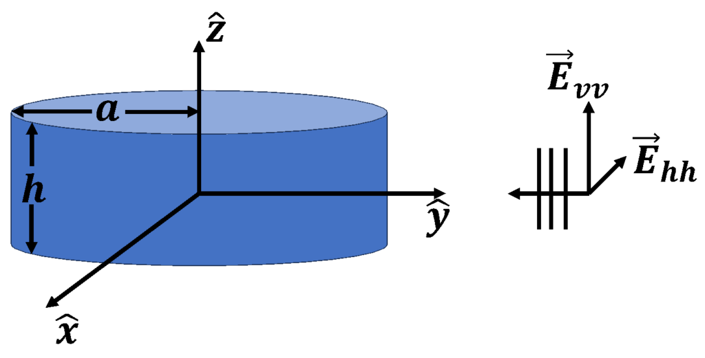
and  respectively. A diagram of the “900” incident field configuration and frequency response from 100 MHz to 6 GHz is shown in Figure 1 and Figure 2 respectively. The “900” model was selected as it is the principal calibration cylinder in use for RCS ranges operating from 2-18 GHz.

Figure 1. “900” squat cylinder incident field configuration.

Figure 2. “900” cylinder frequency response for VV and HH polarization
The position of  in the denominator of (1) prevents the use of the “900” into the resonance region due to nulls caused by the interaction between the specular response and circular rear edges (VV polarization) and the specular response and creeping wave (HH polarization) as shown in Figure 3. The “900” is typically used as a calibration reference for frequencies greater than 2 GHz (
 ) due to the transition between the resonance and optical regions. The frequency response in Figure 2 may be plotted with respect to
  , identifying the Rayleigh, resonance, and optical scattering regions as shown in Figure 4 [8].

Figure 3. Scattered field sources for squat cylinder shown by red arrows for VV (left) and HH (right) polarization.

Figure 4. “900” cylinder frequency response as a function of  identifying Rayleigh, resonance, and optical regions of scattering behavior.
Thus, the goal of any alternative reference must be to either shift resonance nulls as in [3] or reduce null depth through reduction of mechanism interaction with the specular term.
A geometry for the SQD as compared to the “900” cylinder is shown in Figure 5. The radius is the same for each cylinder, providing an opportunity to compare near resonance regions on a similar basis. The SQD height is  as compared to the “900” height of
  , a fabrication requirement to fully accommodate the dihedral geometry without any remaining cylinder surface seen from the dihedral aspect. The moment method RCS for both SQD cylinder and dihedral aspects is shown in Figure 6. As in the case of the “900”, the SQD cylinder aspect reveals distinct Rayleigh, resonance, and optical regions while the dihedral aspect has a very limited resonance region dominated by its specular response.

Figure 5. SQD graphics of cylinder and 22.5-degree dihedral.

Figure 6. SQD RCS full-polarimetric prediction for both cylinder and dihedral aspects 100 MHz to 2 GHz.
To better identify advantages of the SQD as compared to the “900”, the PO-normalized [10] RCS of the SQD and “900” cylinders are shown from 1-5 GHz ( ) for VV and HH polarization in Figure 7, and normalized scattered field phase with each cylinder specular term placed at the origin in Figure 8.

Figure 7. SQD cylinder and “900” PO-normalized RCS for VV and HH polarization.
An examination of the interaction between the specular term and other mechanisms for each cylinder is shown by the peak-null rate of decay for the PO-normalized RCS magnitude in Figure 9 (top). Starting beyond the first resonance null, a 2 dB reduction occurs in the peak-null decay for the SQD cylinder over the “900”, thus extending the lower frequency bound of the SQD cylinder from 2 GHz down to 1 GHz. This reduction begins at  and approaches the “900” peak-null performance at
  (2 GHz), marking the transition from resonance to optical region.

Figure 8. SQD cylinder and “900” PO-normalized phase for VV and HH polarization.

Figure 9. Magnitude peak-null rate of decay for SQD and “900” cylinders under VV and HH polarization.
The reduction of magnitude perturbations in the near resonance region for the SQD cylinder can be attributed to two changes in scattering sources with respect to the “900”. Under VV polarization, the top and bottom rear circular edges have been replaced by two alternating oblique 45-degree wedges as shown in Figure 10. The creeping wave, excited under HH polarization, has been modified by the 90-degree transitional corners of the dihedral, also shown in Figure 10. The oblique wedges and transitional corners provide dispersive time responses in contrast to the deterministic time responses of the circular edges and creeping wave terms as shown by the time domain representation centered about 2 GHz in Figure 11. The late time responses of the SQD cylinder show a reduction in scattering versus the “900” and are consistent with observed reductions in peak-null amplitudes previously shown.

Figure 10. SQD design alterations causing reduced magnitude and phase perturbations for the cylinder aspect circled in red.
Dihedral Aspect Considerations
The secondary calibration target for the SQD is a 22.5-degree right dihedral. The full polarization expression of a right dihedral as a function of rotation is reported by [9] as
 , 2
, 2
where  is the resulting full-polarization response of a dihedral due to a rotation of
  with respect to the dihedral seam, based on scattering terms
  and
and  . It can be shown from (2) that for
  degrees, all four polarizations become equal in the high frequency limit.
Contrary to the cylinder, the dihedral resonance region is well-behaved as the scattering from all secondary mechanisms are small compared to the specular response. The RCS magnitude of the Rayleigh, resonance, and near-optical responses (100 MHz – 4 GHz) are shown in Figure 12 (top), and the full spectrum (100 MHz – 18 GHz) is shown in Figure 12 (bottom). While the dihedral secondary scattering terms are not significant, they are readily seen in the time domain of Figure 13. In the 1-4 GHz time domain response, the HH scattering from the top and bottom front edges of the dihedral is significant with respect to the specular return. However, all secondary sources fall to -40 dB below the specular term in the 4-18 GHz band. The specular response under each polarization clearly dominates all secondary sources in the high frequency region.
Dual-Calibration Considerations
A primary rationale for the development of the SQD is the ability to perform a “Dual-Cal” without the need to access the test zone twice, thereby substantially reducing calibration time and mounting errors. The “Dual-Cal” process modifies (1) through the introduction of a secondary reference measurement and its predicted response according to
 , 3
, 3
where  is the “Dual-Cal” ratio,
  and
and  are the measured scattered fields from reference one and reference two respectively, and
  and
and  are the predicted responses of reference one and reference two respectively. In a system with no error,
  would result in unity.
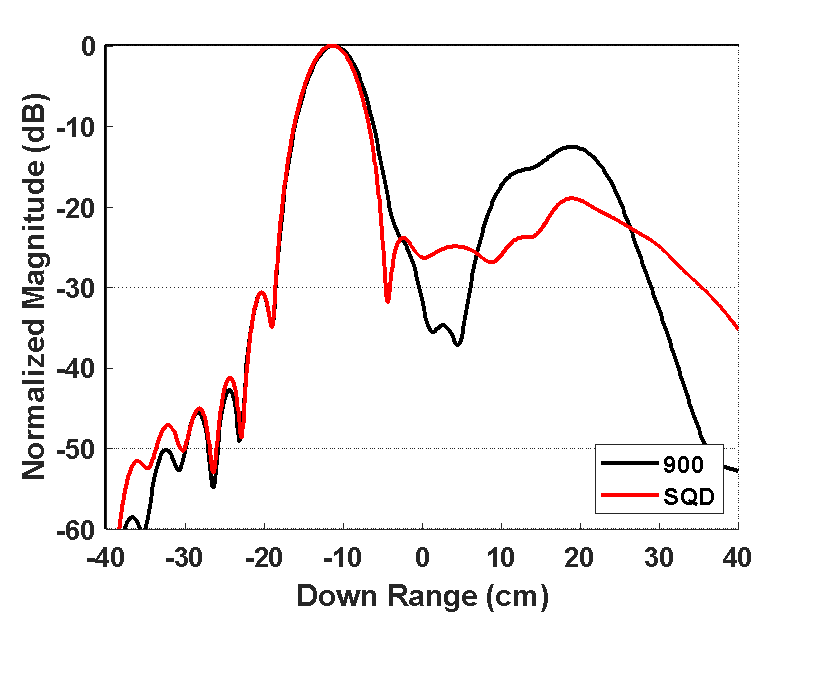
Figure 11. Time domain response of the “900” vs SQD cylinders centered at 2 GHz under VV polarization (top) and HH polarization (bottom).
The usable bandwidth for a pair of “Dual-Cal” reference measurements is demonstrated by the comparison of the measurement ratio in (3) using the predicted solutions of the AFRL squat cylinders 750/900 and the SQD cylinder/dihedral shown in Figure 14. The reference measurement ratio for the SQD is well-behaved down to 750 MHz at VV polarization and 100 MHz for HH polarization, demonstrating substantially more usable bandwidth over the squat cylinder ratio which degrades quickly below 2 GHz.
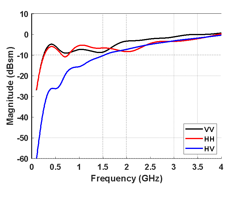
Figure 12. Full polarimetric RCS of SQD dihedral aspect from 100 MHz to 4 GHz (top) and 100 MHz to 18 GHz (bottom)
SQD designed for 500 MHz
The SQD presented thus far has been for design and performance comparisons with traditional squat cylinders. The need exists to provide an SQD with capability down to 500 MHz, as the current model ( and
and  ) performs only to 1 GHz. The design for the modified SQD at 500 MHz can be readily done by scaling the original dimensions up by a factor of two (
 and
and  ). Such a design is fit for mounting on foam columns without regard to internal modifications with top and bottom surfaces flat and unperturbed.
Many RCS chambers, however, use ogive pylons with non-removable top hat rotators (THR). Unlike the squat cylinder, whose internal volume easily accommodates the insertion of a THR, the SQD internal volume is occupied in part by the presence of the 90-degree dihedral plates, the bottom of which limits the diameter of the top hat rotator cannister as shown in Figure 15. The current design requirement for 500 MHz in concert with an internal THR insert mandated an SQD with  and
and  . The RCS of the modified SQD is shown in Figure 16, demonstrating usable bandwidth down to 250 MHz. A rendering of the fabricated 500 MHz SQD mounted on an ogive pylon with THR is shown in Figure 17.
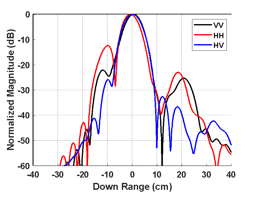
Figure 13. Full-polarimetric time domain response of SQD dihedral aspect 1-4 GHz (top) and 4-18 GHz (bottom).

Figure 14. “Dual-Cal” ratio between AFRL 750/900 and SQD cylinder/dihedral.

Figure 15. Diagram of SQD internal volume with THR inserted showing potential interference points between THR cannister and dihedral faces marked in red.

Figure 16. Full polarimetric RCS magnitude of the modified 500 MHz SQD designed for THR insertion.

Figure 17. Rendering of the fabricated 500 MHz SQD mounted on ogive pylon with THR.
Conclusion
A squat cylinder-dihedral (SQD) calibration device has been presented for use in RCS ranges at UHF. The frequency and time domain responses of the SQD in the resonance region were shown to be superior to the traditional squat cylinder, with reduced contributions from non-specular secondary scattering sources. The combined geometry of a cylinder and dihedral in the same form factor reduces the time required for calibration, especially in larger RCS ranges. The ratio of the SQD cylinder to its dihedral was shown extend the lower frequency bound by at least 50%.
Fabrication of the SQD requires no internal modification when mounted on foam columns. However, the radius of the SQD must be artificially extended to accommodate the insertion of top hat rotators to avoid interference between the top hat cannister and internal dihedral faces.
The SQD provides a means of performing the “Dual-Cal” procedure required by the National RCS Measurement Facilities Certification Program. Ranges who participate in this program, can utilize the SQD to extend their calibration bandwidth and reduce reference target mounting time and error through a single geometry.
References
- H. M. Chizever, R. J. Soerens and B. M. Kent, “On reducing primary calibration errors in radar cross section measurement,” Proc. Ant. Meas. Technique Assoc., pp. 383-388, Seattle, WA, Sept. 1996.
- National RCS Measurement Facilities Certification Program. Handbook of Procedures and Guidance (Draft).Ver 0.2.12, 12 Dec 2021. Pg 47.
- W. Wood, P. Collins, and T. Conn, “The “Cam” RCS Dual-Cal Standard,” in Proceedings AMTA, Washington, DC, Oct. 2004, pp.400-403.
- B. M. Kent, “Comparative measurements of precision radar cross section (RCS) calibration targets,” IEEE Antennas and Propagation Society International Symposium. 2001 Digest. Held in conjunction with: USNC/URSI National Radio Science Meeting (Cat. No.01CH37229), Boston, MA, USA, 2001, pp. 412-415 vol.4, doi: 10.1109/APS.2001.959486.
- L. A. Muth, “Calibration standards and uncertainties in radar cross section measurements,” Proceedings of the 1999 IEEE Radar Conference. Radar into the Next Millennium (Cat. No.99CH36249), Waltham, MA, USA, 1999, pp. 326-331, doi: 10.1109/NRC.1999.767360.
- P. S. P. Wei, A. W. Reed, C. N. Ericksen and R. K. Schuessler, “Measurements and Calibrations of Larger Squat Cylinders,” in IEEE Antennas and Propagation Magazine, vol. 51, no. 2, pp. 205-212, April 2009, doi: 10.1109/MAP.2009.5162070.
- X. Xu, Z. Xie and F. He, “Fast and Accurate RCS Calculation for Squat Cylinder Calibrators [Measurements Corner],” in IEEE Antennas and Propagation Magazine, vol. 57, no. 1, pp. 33-41, Feb. 2015, doi: 10.1109/MAP.2015.2401760.
- Balanis Constantine A. Advanced Engineering Electromagnetics. 2nd ed. John Wiley & Sons 2012. Pg. 662.
- T. Dallmann and D. Heberling, “Discrimination of scattering mechanisms via polarimetric rcs imaging [measurements corner],” in IEEE Antennas and Propagation Magazine, vol. 56, no. 3, pp. 154-165, June 2014, doi: 10.1109/MAP.2014.6867696.
- Knott Eugene F et al. Radar Cross Section. 2nd ed. Artech House 1993. Pg. 196.

