RCS Measurements For In-Process Verification
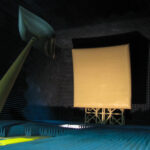
DSC has completed the installation of a turnkey RCS measurement system that is used for in-process verification (IPV) and final component validation using standard near-field QC techniques in an echoic chamber. The delivered system included a radar, antennas, shroud, ogive pylon, foam column, elevators for each – column and pylon, automated pit covers, test bodies, target transport carts, and calibration targets. The system automatically loads test objects on the correct target support system, requiring no action by the operator to connect a target onto the azimuth over elevation “tophat” positioner – it is all automatic.
The user interface is designed to be operated by production line workers, greatly reducing the need for experienced RCS test engineers. Simple pass/fail indicators are shown to the test technicians, while a full detailed data set is stored for engineering review and analysis. A wall display guides users through a test sequence for target handling and starting the radar. Radar data collection of all azimuth and elevation angles and target motion are initiated from a single button push. This is followed by all data processing necessary to conduct the ATP on the parts providing a pass/fail report on dozens of parameters.
The application of production line quality automation to RCS measurements improves the repeatability of the measurements, greatly reduces both measurement time as well as overhead time and allows systems operators to become more interchangeable. This highly successful project, which was completed on time and on budget, will be discussed. This discussion will include radar performance, antenna, and shroud design, target handling, data processing, and analysis software, and the control system that automates all the functions that are required for RCS measurements.
Key Factors For Adding Production Line IPV
RCS Measurements
“No Experience Necessary”
- Make RCS measurements using Production Line Technicians
- Answers are the same using a 20-year RCS engineer and a Tech that started last week
High Reliability
- The production grind is relentless
- No time for troubleshooting or repairs
Fast
- Testing every part needs to take WAY less time than the repair time at the existing failure rate
Why Use In-Process Verification (IPV)?
- Find problems early
- There is less invested in the part
- Repair is easier
- Scrap is easier to tolerate (time and money)
- See small changes in RCS before they are a problem
- Minor process changes (new person?) or machine wear
- Components are known as good before being applied to aircraft
Delta Sigma Company can do your Chamber Planning, including
- Chamber Design
- Antenna Design
- Shroud Design
- Radar Design
- Pylon, Column, & Rotator Designs
- Elevator & Tilt Mechanism & Pit Cover Designs
- Integrated System Control Software
- Data Processing Software
Delta Sigma designs and builds Automated RCS Measurement Systems
- 1 button push for:
- Chamber Door opens
- Automatic Target loading
- Chamber Door Closes
- Automatic collection of all frequencies/polarizations/LDA’s/AZ angles
- Automatic data processing of all above
- Automatic comparison to standard for pass/fail for all above
- Automatic display to an operator of pass/fail
- Automatic Target unloading
- The user does not affect the test process!
Production Line Measurements Must Reduce User Skill Requirements
- User skills still needed (probably) to
- attach item-under-test to test fixture
- If the test result = fail
- Assess if failure is due to part or part/fixture interface
- Repair interface if necessary
- Engineering skill still needed if result = fail
- But this expertise is not needed in the test chamber
- Hopefully, rarely needed
Automatic Target Support Selection
- Some parts are mounted into a test fixture for RCS testing
- Some parts sit atop a foam column for RCS testing
- The system auto-selects the correct one based on the part being tested
Automatic Target Loading
- The user pushes a cart with a loaded test fixture to the chamber
- The cart is on air bearings
- 700 pounds – less than 10 pounds of force to push
- The cart is guided to the proper position
- Cart/pit-covers interface forces proper alignment
- Sensors detect in-position
- Pylon raises while the operator holds a wireless “live-man switch”
- Target is engaged and locked automatically
- The operator removes the empty cart
- Pylon raises to full height and tilts to test the position
- Rotator moves to starting AZ and EL position
Automatic Data Collection
- Once the Pylon and Rotator are in position the radar starts data collection
- The frequency range can include any band desired
- The number of steps in a chirp can be 2 to 65k
- After all waveforms at a given EL angle are complete, the system moves to the next EL angle
- Repeat until all EL angles are complete
Automatic Data Processing/Compare to Standard
- Data processing is real-time
- A 2D ISAR image is produced a second or so after the last chirp is collected at every angle of interest
- Boxes are placed in the key positions on the image to obtain “box scores”
- Box scores are compared to the same box in the Standards data
- Pass/fail is determined for numerous criteria (boxes)
Automatic Pass/Fail
- If any box fails, the part fails
- A massive amount of data is available to engineers for RCS diagnostics
- Determine the repair process or scrap
- If all boxes pass, the part passes and moves to the next step of the build process
Automatic Target Unload
- The user pushes the empty cart into the chamber
- The cart is guided to the proper position
- The pylon will have already lowered to just above cart height
- Pylon lowers while the operator holds a wireless “live-man switch”
Target is unlocked and disengaged automatically
- The operator removes the loaded cart
Assorted Pylons
Rotators
| Rotator | DSC 1 | DSC 2 | DSC 3 | DSC 4 | DSC 5 | DSC 6 | DSC 7 | DSC 8 | DSC 9 |
| Capacity (lbs) | 3000 | 4000 | 3000 | 1500 | 500 | 1500 | 750 | 4000 | 4000 |
| Diameter (in) | 14 | 26 | 15.25 | 14 | 8.5 | 12.86 | 12.86 | NA | 4 |
| Height (in) | 4.5 | 6 | 5.95 | 7.5 | 6.25 | 4.5 | 4.5 | NA | 6 |
| Horiz CG Offset (in) | 2 | _ | 1 | 1 | 1 | 2 | 2 | 2 | 2 |
| Vert CG Offset (in) | 18 | _ | 9 | 9 | 12 | 18 | 18 | 12 | 12 |
| EL Range (deg) | -5 to 40 | 0 to 25 | -5 to 20 | -5 to 20 | -1 to 45 | -1 to 45 | -1 to 45 | NA | -16 to 16 |